PEBBLE - Picaxe Electronic Bread Board Layout Emulator

slurp

Senior Member
Offset Resistors?

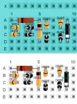
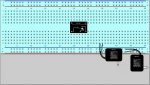
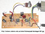
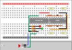
Ok, this isn't a finished circuit but it's made some use of the bent and insulated wire ends. The tip is to pick up the wire and replace it on the board once you've tweaked it so that it snaps into the right place....

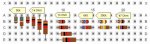
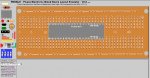
I'm ignoring the power rails as I don't have them on my board and I've tried to simulate LED with the limiting resistor soldered as a space saving trick. I think it looks ok but an offset might be useful (like the wires) to help reveal connections to the holes below.

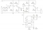
These new bent and offset wire mean that we don't need anything other than straight ends on the switch. This in turn would give more flexibility on placement and wire connections to the board. I'd like to make another switch connection to I2, it's going to be odd but the straight termination on the switch could make this easier. (current wire offsets allow us to align with the switch terminations).

The more I use this the more I like it, I loved it before!

regards,
colin

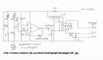
Code for this circuit:-

Code:
IC||766|270|1|L293D|U?|||L293D|IC||L293D_1
IC||524|270|1|PICAXE 18X|U?|||PICAXE18|IC||PICAXE18_1
Wire||856|240|11||11|#000000|1|11|||
Wire||856|377|11||11|#000000|1|11|||
Wire||883|399|11||11|#000000|4|12|||
Wire||883|212|11||11|#000000|4|14|||
Wire||979|212|22||22|#000000|7|33|||
Wire||748|377|11||11|#CC6633|2|11|||
Wire||748|240|11||11|#CC6633|2|11|||
Wire||721|368|12||11|#CC6633|8|11|||
Wire||721|243|13||11|#CC6633|8|11|||
Wire||640|212|11||11|#FF0000|5|11|||
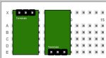
Note||913|149|1||||||Motor 1||NOTEPAD_1
Note||764|149|2||||||Motor 1||NOTEPAD_2
Note||762|452|2||||||Motor 2||NOTEPAD_2
Note||915|451|1||||||Motor 2||NOTEPAD_1
Wire||775|408|13||12|#FF9900|8|12|||
Wire||964|240|11||12|#FF9900|1|14|||
Wire||989|240|21||23|#FF9900|6|33|||
LED|0|640|366|1|LED|LED?|1|||IC||led_11
Resistor|330|535|373|1|Resistor|R?||2||IC||
Wire||602|377|11||12|#000000|1|33|||
Wire||506|377|11||13|#000000|1|13|||
Wire||506|435|13||12|#000000|5|11|||
LED|0|667|394|1|LED|LED?|2|||IC||led_21
Resistor|330|535|401|1|Resistor|R?||2||IC||
Wire||506|405|11||11|#000000|1|13|||
Wire||602|405|11||12|#000000|2|33|||
Switch||388|595|1||SW?|1||1|Switch||switch_111
Wire||504|462|21||12|#3253FF|5|13|||
Wire||531|463|13||21|#00A060|3|41|||
Wire||531|469|21||32|#00A060|5|33|||
Resistor|47000|535|428|1|Resistor|R?||2||IC||
Wire||512|249|23||32|#00A060|7|44|||
Wire||522|243|13||11|#00A060|4|31|||
Wire||513|432|11||33|#00A060|1|33|||
BREADBOARDSTYLE=BB10
 

Attachments

westaust55

Moderator
PEBBLE - 1 span resistors and diodes

Westaust --- thanks for all the work you've done with PEBBLE.
I have a request (hope it's not a daft one) Is it possible to have a vertical resistor/diode.Sometimes space is at a premium and I just want to span a single space between two holes
thanks.
Hi Pilko,

Yes resistors and diodes with a span of 1 have previously been requested and are included on the wish list a some posts back. Should be included in a Rev 2.2 in about a week.
 

moxhamj

New Member
Slurp, that is one nice looking breadboard! The new bendy wires really make a lot more complex circuits possible.
 

westaust55

Moderator
PEBBLE - single span diodes

Had a quick lunchtime play with a vertically orientated diode image.

Very rough as done with MS Paint but the concept looks okay.

Will work on the vertical diode images more tonight . . .

A resistor will be more fun to code but as a concept in MS Paint
 

Attachments

Last edited:

westaust55

Moderator
PEBBLE - 1 span vertical oriented diodes now done

Created the images and code for the requested 1 span (vertically mounted) diodes . . . . (will be included in the next release)

will look at the vertical resistors next. As mentioned, will be more fun as they are drawn by "maths" not images. Still aiming to retain the colour bands, but may prove to be the least realistic component images :eek:
 

Attachments

Last edited:

slurp

Senior Member
Invisible Holes

I missed a comment in #241, if I placed the end of the IC in column 30 then we can not wire around the bottom as depicted. This could be resolved if we had another set of snap points (invisible holes?!?) as it gives the ability to use the edge for wiring.

I'm thinking about the switch issue again, I'll look at spinning 90 degrees and snap positions for wires (will give it ago this evening). It's fantastic what Westy has crammed into this already.

Best regards,
colin
 

manuka

Senior Member
Tarah- single span "pigtailed" resistors, c/w colour coding. I've uploaded this on his behalf, as Westy is again being Forum thwarted. The problem seemingly relates to 9pm log on times at his Perth (WA) location.
 

Attachments

westaust55

Moderator
PEBBLE - a status update

Thanks for doing that upload/announcement last night for me Stan.
Yes not sure on the exact cause but have noted that each time it occurs, I lose access to this forum at exactly 9pm Perth time (1pm UK time), even if already logged in and typing up a post. But can then take few days to regain access.
Attached is a summary of what has been done and what I propose to complete for the next revision (V2.2).
 

Attachments

Last edited:

slurp

Senior Member
Drew up an image for a CR2032 battery and included the necessary code in various files.
This looks like a spot the difference competition... I noted the regulator has been fitted to the rigth hand picture but not the lefthand one! ;)

regards,
colin
 

moxhamj

New Member
Yes I've got a CR2032 and it is like the picture on the right. You end up with one hole free at the top and one at the bottom. So a perfect fit! The pebble image on the left is ? just a fraction big.
 

moxhamj

New Member
Perfect! I gather the 2032 is a cheap and cheerful supply for a picaxe? I've been buying quite a few for RAM battery backup and Futurlec sell the battery for 30c and the holder for 18c. Search Hardware/Batteries/Coin.
 

westaust55

Moderator
CR2032 batteries

Futurlec have had a recent 30% price increase - CR2032 now AUD$0-40 ea :eek:

MicroZed sell the CR2032 battery at AUD$1-80 ea or 10 for $15 and the battery holders at AUD$0-90ea.

Still higher than Futurlec but local.

Jaycar is extortionate at ~AUD$2-50 per battery
but wait . . .
Altronics (cat S4999) at AUD$4-55ea ! :rolleyes:
 
Last edited:

manuka

Senior Member
Aside from PVs & supercaps,you certainly can't beat the compactness & utility of coin cells. For PICAXE work, with a CR2032 typically rated ~200mAh, a low drain/sleeping/BOD enabled circuit may run for weeks. Here in NZ,coin shops often have 6 pak cards of them (hitting or past their use by date) for ~US$1. That 2032 coding relates to 20mm diameter & 3.2mm thickness by the way, & CR denotes Manganese dioxide Lithium chemistry.

I've long been wary about devices/projects powered by coin cell batteries however, as they may indeed cost an arm & a leg - US$3 is typical at supermarkets & pharmacies- or be unobtainable in the field. They're a tad too easily shorted too- I recall an ESD aware PC service trainee carefully wrapping one in aluminium foil ! Stan
 

westaust55

Moderator
I am sorry if this has been asked... I searched the thread. How do you paste???
the standard keyboard shortcuts apply (as per most programs)
Ctrl-X to cut or remove
Ctrl-C to copy (without removing form original)
Ctrl-V to paste at the cursor/mouse/highlighted position
 

slurp

Senior Member
Ctrl-A is also useful as select all... make sure you click in the right window first!

regards,
colin
 

pixelsaurus

New Member
I think this is a great toy to play with. Thanks for all your efforts westaust55. The only glitch that I have experienced so far is when sometimes I edit a component, the pop up menu "sticks" to the cursor. I have to double click it to get it to stay put. I'm using IE*8. Once again, thanks.
 

westaust55

Moderator
Hi Pixelsaurus,
Firstly, albeit as a member for some time, as your first post on this forum, welcome to the PICAXE forum.
Thank you for the encouraging words. Hope that you find it useful in your projects.

Once I have the next round of components and program adjustments made I can look into the IE8 “sticky” edit windows.
Has anyone else by perchance found this same problem? :confused:
 

pixelsaurus

New Member
Thanks cobber. It was propitious that I found your emulator and my old breadboard at the same time. I'm currently working on a programmable camera timer and was not keen on the idea of soldering up a prototype. Pebble now makes every thing easy peasy. Thanks again.
 

AlainB

New Member
Hi,

I must say that I really enjoy using PEBBLE. Thanks for everything!

I managed to understand at least partially how the code is working and I like the fact that it is not too hard to customize.

While waiting for your beautifull drawings I made a few of my own of lesser quality that I included in the miscell sections, starting at "misc_1000". This way I dont have to swap any of your drawings for mine.

My wish list would include a board like this one, that is the exact representation of all my boards, except for the color and the length. My boards have 64 holes. But 50 holes is quite enough. With this light turquoise color, all the wires colors are easily seen. Having 6 pins (triac drivers) and even 4 pins (Optocouplers) DIP would also be on my wish list.

I can see that this work will never end for you. There are zillions of parts that can be added. Maybe a small tutorial on how to customize the program to add a part would be helpfull and would relieve you of some work.

Thanks again!

Alain
 

Attachments

Last edited:

westaust55

Moderator
PEBBLE

Hi Alain,

Thanks for the feedback.

Yes I can add DIP packages for 6 pins (triac drivers) and 4 pins (Optocouplers).
If you already have some images, feel free to send them to me or post here in say a zip file and I can look at including same.

As you say for simple components, it is easy for people to add their own extras needing just an image and entires into from 2 to 4 of the script files depending upon text placement etc.
Maths for wires and reistors are the only complex type of programming.

As you say, this can go on forever. However I do have another project I am about to get onto within a few days so progress here will start to slow down.
 

westaust55

Moderator
PEBBLE - improve terminal strip details

I have spent a couple of hours to remove the transparent area around all the terminal strip images and adjusted the code acordingly.

This means amongst other things that the 3-way header pin when dragged over from the menu will be correctly positioned over the holes imemdiately.

Also took the opportunity to put the user text for the SIL modules inside the module image and close to the terminal strip so it can be used to either
(a) identify each terminal, or
(b) give the module a name/title.
 

Attachments

Last edited:

westaust55

Moderator
PEBBLE - More ICs included

As requested, today I have included the following additional DIP IC chips:
- 555 Timer
- 4 pin DIP (blank)
- 6 pin DIP (blank)
- 4 pin opto coupler ( transistor output style)
- 6 pin opto coupler (MOC2030 triac output style)

have fun . . . . :)

Next will be to add some keypads (but not today) . . . .
 

Attachments

tiscando

Senior Member
There are also 8-pin optocouplers e.g: 6n136 (cream-colour) and 6n139 (black).

Wow, this thread is racing to the top of the no. of replies leaderboard (what appears when the threads are sorted by no. of replies, descending, from the beginning), and it is now 10 replies away from overtaking 'pulsin then servo' to be at the top of the leaderboard with over 282 replies! And it would easily do because it is talking about a new piece of software which is updated almost endlessly.

I like this interesting breadboard emulator, although I haven't got it yet. I will try and get it when I need to design breadboard prototypes on the computer.

Thank you for your hard work Westy ;)
 
Last edited:

SilentScreamer

Senior Member
+1 reply -- 8 more to go :D

As this is designed to be run off-line would it be better to make a group of components known as "custom" and a tutorial on how to add the new component to the CSS scripts. We could also have another thread or use this thread for posts containing images and the modifications for user made components. Then additions are only needed for new PICAXEs and any new chips that become very commonly used.
 

westaust55

Moderator
PEBBLE

+1 reply -- 8 more to go :D

As this is designed to be run off-line would it be better to make a group of components known as "custom" and a tutorial on how to add the new component to the CSS scripts. We could also have another thread or use this thread for posts containing images and the modifications for user made components. Then additions are only needed for new PICAXEs and any new chips that become very commonly used.
There are already blank variants of each IC size so if the inbuilt versions do not suit then use a blank and add the chip IC part number.

Yes, in due couse (don't ya love them words) I can prepare some words on what is involved to add your own components. Additional specific IC's are probably the easiest for others to add with very little effort.

Once I have V2.2 released, I think it will slow down / become stable (as I am about to get into another project). Then Rev Ed will host as well. Maybe they can set up a section, or users in general can have a thread in one of the finished project areas, set aside for posting new component images. Then lets see who is first to put a non image post there :rolleyes:
Maybe a separate thread for wish list items, which I or others, can tackle as time permits.

have fun . . . . .
 

westaust55

Moderator
PEBBLE - latest breadboard

last night I started to add the Dick Smith Electronics paxolin based 45 row cat No H-6505 proto board to the bread board library.
manuka informs me that this board has been a regular in many schools and is quite cheap to purchase.

Still to tweak the maths to the placed component leads align optimally with the image holes.

Will also work on another DSE board, a green fibreglass 30 row variant that I use and have mentioned in the past on this forum with a different hole format.
 

Attachments

manuka

Senior Member
Thanks Westie for the H-5605 image - its certainly NOT my favourite soldered prototype board however! Give me Kiwi Patch Board any day. On appearance alone fi-glass types will now always win out (Paxolin is so 1960s), & I'd really only asked for it due to the no doubt extensive stocks at many schools & hobbyists. Hence refer the attached 08M seismometer circuit from => http://science.uniserve.edu.au/school/Seismograph/datalogger I'm predictably not wild about their layout assembly- it'd be a good PEBBLE prospect in fact!).

H-5605 is pretty cost effective however, even at ~Aust$3 a board, as when suitably sliced into portions perhaps up to 4 simple PICAXE-08M circuits can be mounted. Of course this is where PEBBLE again comes in,since it'll allow juggling of board real estate to suit. Stan
 

Attachments

Last edited:
Top