Water drop controller
- Thread starter bfgstew
- Start date
I'll have to leave this to people more PICAXE-savvy than me.
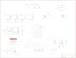
In standard schematics when you give a wire a label it is joined (in netlist) to any other wire with the same label.
Hence my confusion and that there is no obvious schematic connection to the PICAXE pins.
You should bring out stubs from the Micro with the appropriate labels attached.
You've done it with the power lines but not on B.1 etc.
What CAD are you using?
bfgstew
Senior Member
Yes Busby that is correct, works as power on to the LM386.Pin 6 of the LM386 ( Vs ) is connected to C.0 on the schematic.
Is that correct ?
bfgstew
Senior Member
Sorry Dippy, thats just me, I did it that way thinking it would leave less confusion if I labelled up everything going to where it goes, I thought it was OK? Never mind will re do it so it reads easier.I'll have to leave this to people more PICAXE-savvy than me.
In standard schematics when you give a wire a label it is joined (in netlist) to any other wire with the same label.
Hence my confusion and that there is no obvious schematic connection to the PICAXE pins.
You should bring out stubs from the Micro with the appropriate labels attached.
You've done it with the power lines but not on B.1 etc.
What CAD are you using?
Using Eagle for schematic, PCB was done with Designspark
bfgstew
Senior Member
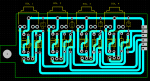
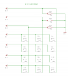
I could understand it if it was just pins A.0 to A.3 going wrong. All solenoids have back EMF protection using IN4001 diodes and driven using IRF510 FET'sMultiple pin failures to match multiple solenoids?
How are you driving the solenoids?
Do you have reverse EMF protection?
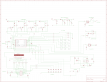
Further updated schematic with all inputs and outputs connected.
bfgstew
Senior Member
Keypad I am using from Tech-supplies - KEYPAD
Pin set up for same keypad -
Keyscan code -
Pin set up for same keypad -
Code:
symbol SOUND_ON = C.0
symbol SOUND_IN = C.2
symbol PG_ON = C.1
symbol LIGHT_IN = C.3
symbol LIGHT_ON = C.4
symbol FLASH = C.5
symbol CAMERA = C.6
symbol PG_IN = C.7
symbol SOL1 = A.0
symbol SOL2 = A.1
symbol SOL3 = A.2
symbol SOL4 = A.3
symbol COL2 = pinB.0
symbol ROW1 = B.1
symbol COL1 = pinB.2
symbol ROW4 = B.3
symbol COL3 = pinB.4
symbol ROW3 = B.5
symbol ROW2 = B.6
Code:
GKP:
 	 Do
    		Gosub GTKP			' Wait until no key pressed
  			Loop Until key_value = 0
 	 Do
   		 Gosub GTKP			' Wait until key pressed
  			Loop Until key_value <> 0
  			If key_value = 11 Then
    			key_value = 0
  		End If
  	Return
GTKP:	;Keypad scan coding
		key_pos = 0
		key_value = 0
	 	High ROW1 : gosub ScanCol : low ROW1
	 	High ROW2 : gosub ScanCol : low ROW2
	 	High ROW3 : gosub ScanCol : low ROW3
	 	High ROW4 : gosub ScanCol : low ROW4
	 	Return
	 	ScanCol:
	 		if COL1 = 1 then : key_value = key_pos + 1 : endif
	 		if COL2 = 1 then : key_value = key_pos + 2 : endif
	 		if COL3 = 1 then : key_value = key_pos + 3 : endif
	 		key_pos = key_pos + 3
   		return
hippy
Ex-Staff (retired)
It does seem odd. Though B.x pins could produce shorts between output high and low depending on buttons pushed, that should not affect the A.x pins, and not just one.I could understand it if it was just pins A.0 to A.3 going wrong.
bfgstew
Senior Member
It does seem rather odd Hippy, I think what I need to do is order a few more 28X2 chips and see what happens.
Is there any other tests I could do on these chips to asertain what is wrong? I did run a code to check them.
do
let pinsA = % 00011111
let pinsB = %11111111
let pinsC = %11111111
pause 1000
let pinsA = %00000000
let pinsB = %00000000
let pinsC = %00000000
loop
connected an LED to 0v to see if it blinks.
hippy
Ex-Staff (retired)
You are never setting the pins to be output so that may be a problem ;-)
This is the sort of test I use; it puts 1 pulse on pin 0, 2 pulses on pin 1 ... 8 pulses on pin 7. Check with a LED that each pin flashes in turn. It would be worth testing low pulses if trying to find what does or does not work.
This is the sort of test I use; it puts 1 pulse on pin 0, 2 pulses on pin 1 ... 8 pulses on pin 7. Check with a LED that each pin flashes in turn. It would be worth testing low pulses if trying to find what does or does not work.
Code:
Do
  dirsB = $FF
  b1 = 1
  For b0 = 0 To 7
    b2 = b0 + 1
    For b3 = 1 To b2
      pinsB = b1 : Pause 250
      pinsB = 0  : Pause 250
    Next
    b1 = b1 * 2
  Next
Loop
bfgstew
Senior Member
Sorry that should read 'using dirsA, dirsB and dirsC'.Same results hippy on dirsA, dirsB and DirsC............?
Also tried the same but as inputs and the same pins are not working, looks like I now have a brace of duff 28X2 chips!!!!
bfgstew
Senior Member
I certainly have Buzby.Have you got an oscilloscope ?.
Buzby
Senior Member
Great !.
If you monitor each IO pin you should see what 'high' and 'low' levels look like as the code is running.
They should be close to the supply and ground voltages, as long as not too much current is being pulled.
You need to check each pin as you press every button.
If you see a pulse in the waveform which has a significantly lower or higher voltage than the others, then you have a clue as to where to start looking.
It is going to take a combination of hardware and software checks to get to the bottom of this, have you posted the full code recently ?
bfgstew
Senior Member
OK Buzby, It will be later tonight or tomorrow before I can do any checks, but will have a look at the keypad I/O's as you say.
Unfortunately the code is rather large and is spread over 4 slots so unable to post the full code unless it's done using a zip file, but I did post the keyscan code a few posts back and the pin configuration as well.
Unfortunately the code is rather large and is spread over 4 slots so unable to post the full code unless it's done using a zip file, but I did post the keyscan code a few posts back and the pin configuration as well.
Hi Stewart,So, any ideas how and why this has happened please?
It does appear that if you press two keyboard buttons at the same time then two strobe outputs (one high, one low) can be linked together. I thought that the keyboard uses "conductive rubber" so I'm surprised that there is enough current to damage a PIC, but perhaps it's very "good" conductive rubber
")
The normal "fix" for such a problem would be to put a resistor or diode in series with each output pin. However, if you want a software-only fix (to avoid changing the hardware) you might be able to set the "quiescent" state of the strobes as an "input" instead of Low. Then strobe each pin High (i.e. output), making the previous pin an input again. But that will only cure the "two buttons pressed" issue, not protect against any other cause of high currents in the pins (which should be cured by series resistors).
Cheers, Alan.
bfgstew
Senior Member
OK hooked up to oscilliscope but pins B.1 and B.3 look like they have packed up on this chip as well and I have no more 28X2's!!!!!!!!!!!!!!!!!!!
Pin B.0 sits at 0v until keys 2 and 0 are pressed, then voltage is oscillating between 0v and 5v.
Pin B.1 oscillates to 5v and nothing happens on key press
Pin B.2 sits at 0v until keys 1 and * are pressed, then voltage is oscillating between 0v and 5v.
Pin B.3 oscillates between 2.5v and 5v until keys *, 0 and # are pressed the voltage oscillates between 0v and 5v.
Pin B.4 sits at 0v until keys 3 and # are pressed, then voltage is oscillating between 0v and 5v.
Pin B.5 sits at 2.5v until keys 7, 8 and 9 are pressed then voltage drops to 0v while key is pressed.
Pin B.6 sits at 2.5v until keys 4, 5 and 6 are pressed then voltage drops to 0v while key is pressed.
Sorry this looks a bit vague, just hope this can be deciphered ino some tangible clue?
hippy
Ex-Staff (retired)
Those are your output pins driving the keypad matrix. Sitting at 2.5V suggests a short somewhere, 0V fighting 5V.Pin B.3 oscillates between 2.5v and 5v
Pin B.5 sits at 2.5v
Pin B.6 sits at 2.5v
Hi Stewart,Sitting at 2.5V suggests a short somewhere, 0V fighting 5V.
Yes, try touching a load resistor of say 1k ohms from the pin to ground or supply. If the voltage changes dramatically then the pin is probably Open Circuit (floating). However, 2.5 volts sounds more like two "alive" pins fighting each other, so maybe the chip isn't dead (yet).
Good luck, Alan.
Buzby
Senior Member
Hi Stewart,
I think we really need to see all the code. It does look like fighting pins somewhere.
The pins going belly-up are connected to OLED as well as keyboard.
[Edit, I wrote rubbish before ! ]
Don't plug a new chip in until the full code has been checked !.
Cheers,
Buzby
Additional question - Is the keypad a 'clicky disk' type, or a conductive rubber ?
Attachments
-
 5.5 KB Views: 14
Last edited:
bfgstew
Senior Member
Buzby
Senior Member
Hi Stewart,
I have looked through the 4 slots of code that you posted, and can't see any obvious IO fighting.
Has anyone else had a look ?
My suggestion is that you build a daughter board.
Just a 28X2 in a socket, with long pins to fit into the motherboard socket where the original 28X2 would sit.
But replace the 'long pins' for the IO with 330R resistors.
This will protect your 28X2 from further damage while we try to find the problem.
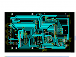
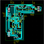
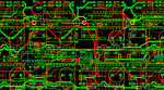
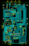
Please post a better picture of your PCB. The current one is too coarse, it looks like you've go too many shorts to run at all !.
Cheers,
Buzby
I have looked through the 4 slots of code that you posted, and can't see any obvious IO fighting.
Has anyone else had a look ?
My suggestion is that you build a daughter board.
Just a 28X2 in a socket, with long pins to fit into the motherboard socket where the original 28X2 would sit.
But replace the 'long pins' for the IO with 330R resistors.
This will protect your 28X2 from further damage while we try to find the problem.
Please post a better picture of your PCB. The current one is too coarse, it looks like you've go too many shorts to run at all !.
Cheers,
Buzby
Buzby
Senior Member
Hi Stewart,
For grabbing screen images I use this : http://bluefive.pair.com/snapshot.htm
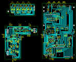
So get your PCBs on your screen, individual ones as big as you can, then callup up Snapshot, then save as .png.
That's the way I do it.
Cheers,
Buzby
For grabbing screen images I use this : http://bluefive.pair.com/snapshot.htm
So get your PCBs on your screen, individual ones as big as you can, then callup up Snapshot, then save as .png.
That's the way I do it.
Cheers,
Buzby
Windows Vista or later also has a program built in called 'Snipping Tool'.For grabbing screen images I use this : http://bluefive.pair.com/snapshot.htm
So get your PCBs on your screen, individual ones as big as you can, then callup up Snapshot, then save as .png.
All versions of Windows can also use the PrintScreen key on the keyboard to copy a screen capture of the screen (or just the current window if Alt+PrintScreen is pressed) which is useful on older versions of Windows if you don't want to use that linked program which has an installer! Simply open Paint and paste the screen capture there - then crop it if necessary and save it as a PNG (not a JPG - that will look awful).
As the PCB was made in DesignSpark PCB, you can use the export facility built into DesignSpark PCB as well. Go to File > Export and choose from Bitmap Image or Metafile Image - the former should really be converted to PNG after saving because bitmap files are large. The metafile option is useful as it saves the design as a vector image so you can stick it in a Word document or PDF and it will look very nice once printed unlike a bitmap which will have horrid pixellated diagonal lines and text. Note: This export feature exports what is currently on screen. If you have the colour scheme set to 'DefaultBlack' (instead of 'Default') but you would rather your exported image is on a white background then temporarily create a new PCB/schematic design using the 'Default' colour scheme (they call it a 'technology file' - you will see it in the dialog that appears when pressing 'New') and copy and paste your PCB or schematic into this new file.