Water drop controller
- Thread starter bfgstew
- Start date
Hi Stewart,
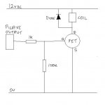
Yes that looks reasonable if you've decided not to use an optocoupler to protect the PICaxe. The diode only needs a rating similar to the coil (I believe 12 volts and some hundreds of mA) so almost any one should do, but I'd be inclined to use a small "power rectifier diode" (e.g. 1N4001) rather than a "signal diode". However, a couple of points:
Generally it would be wise to put a decoupling capacitor across the 12 volts rail, perhaps a few hundred microfarads electrolytic, but it depends on the nature of the Power Supply.
The "protection" diode across the coil may slow the release of the solenoid, perhaps making it as much as 10 times longer than the activation time (this may or may not be significant). So allow for putting a resistor in series with the diode, if required, typically about the same resistance as the coil itself.
Cheers, Alan.
bfgstew
Senior Member
Just an update for anyone interested.
FET's arrived and duly fitted to the board and after a bit of tweaking (removed the 1K resistor from Picaxe output) I now have the solenoid coil firing. Tidied up a few other loose ends and now have the camera trigger working and the flash output as well so a big step forward. Just need to get it all tidied up and fitted correctly in the box, then rig up the Marriot syphon and give it a run in anger.
Will post some pics of rig and box soon.
Stewart
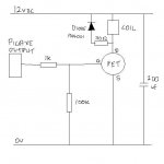
Why did you add the 30Ω resistor in series with the diode? It will actually reduce the effectiveness of the diode.Thanks for that Alan, updated schematic attached just to make sure all is in the correct places and ratings, the coil is only 30 ohms.
View attachment 11270
Stewart
Ken
Hi,Why did you add the 30Ω resistor in series with the diode? It will actually reduce the effectiveness of the diode.
Ken
With only a diode, there is only a low voltage across the coil (when the driver switches off) so the current decays rather slowly (E = -L di/dt) and there can be a delay before the solenoid/valve releases (not necessarily a problem, but it should be considered). With the resistor, the standing current creates an additional voltage drop and thus the current decays (-di/dt) more rapidly. It might not be an issue in this particular case, but the diode is a "classic" way of producing "slow release" relays, etc..
Cheers, Alan.
Hi Stewart,No disrespect to Alan, but it didn't work so I removed that as well.
No offence taken. Do you mean you removed just the resistor and connected the diode directly across the coil, or you removed the diode as well?
In the former case the valve may just stay opened rather longer than programmed, probably not a problem unless you find that you can't program the valve to open for a short enough time.
The diode is basically intended as a protection component; if it's omitted then nearly all the energy stored in (the incuctance of) the solenoid will be dissipated in the FET. Again, this might not cause any problems, but if the circuit does "suddenly stop working" then that might be the cause.
")
Cheers, Alan.
bfgstew
Senior Member
Oh no, left the diode in place, that's a no brainer. It was that I had some problems initialy trying to get the FET to work, so after a lot of head scratching I stripped it as bare as I could and just left the diode in place and it worked. Now during the testing later I shall see how quickly the coil can open and close as it is, if it is too slow I shall pop the 30 ohm resistor back in to see if it helps speed it up, saying that I have had it running dry at a 10ms cycle rate.
Proof of the pudding is in the eating, and I am hoping this is going to taste rather sweet...............
Proof of the pudding is in the eating, and I am hoping this is going to taste rather sweet...............
bfgstew
Senior Member
Well, success with the first trial run. After a lot of setting up to get correct height and drop size I managed to get the drops to collide and catch it on camera. Still need to get the flash and camera delays to work correctly, as I can't get parallel task to work properly as 'start0' has to be at the start of code and I need it at the end, but I am sure I can get around it, but so far so good.
A 'BIG' thank you to all who have helped and guided me so far, much appreciated.
Stewart
A 'BIG' thank you to all who have helped and guided me so far, much appreciated.
Stewart
bfgstew
Senior Member
Further update - decided to add a photogate to the unit now, just add a bit of flexibility to it but have hit a snag.
I added some coding to do the photogate triggering and now my OLED screen is playing up and for the life of me I cant see my mistake, if there is one? If I download to unit, the screen works fine, does what it is supposed to but when I switch the unit off and then on again, the screen is blank apart from a brief flicker, but if I press the keypad a number comes up on screen and I can carry on, it goes through its cycle and then the screen is fine????? What is, or has happened. I have swapped the 18M2 chips just in case it was faulty but no difference.
Any ideas?
Last edited:
Add a pause before LCD initialization.Further update - decided to add a photogate to the unit now, just add a bit of flexibility to it but have hit a snag.
I added some coding to do the photogate triggering and now my OLED screen is playing up and for the life of me I cant see my mistake, if there is one? If I download to unit, the screen works fine, does what it is supposed to but when I switch the unit off and then on again, the screen is blank apart from a brief flicker, but if I press the keypad a number comes up on screen and I can carry on, it goes through its cycle and then the screen is fine????? What is, or has happened. I have swapped the 18M2 chips just in case it was faulty but no difference.
Any ideas?
bfgstew
Senior Member
Went through everything and found the culprit. What I had for initializing the OLED was 500ms but somehow I managed to knock a 0 off it by accident late last night when I was adjusting the code, I assumed it was still there so didn't check until now, so Nick was on the mark again with his diagnosis.
Thanks Nick
Thanks Nick
bfgstew
Senior Member
I am now nearing completion of this project (thank god I can hear you all cry.......) and am crossing the t's and dotting the i's and I still have 1 pin unused, now me being me and not wanting to waste anything was wondering how to use it up and have thought about adding a sound trigger, so it can pick up a soft clap to a bang. I have a few LM386 amplifiers and an old PC mic and was wondering if it could be done using just the last remaining pin C.4 as the input (18M2 chip) and trigger B.6 and B.5 (to flash and camera)?
) and am crossing the t's and dotting the i's and I still have 1 pin unused, now me being me and not wanting to waste anything was wondering how to use it up and have thought about adding a sound trigger, so it can pick up a soft clap to a bang. I have a few LM386 amplifiers and an old PC mic and was wondering if it could be done using just the last remaining pin C.4 as the input (18M2 chip) and trigger B.6 and B.5 (to flash and camera)?bfgstew
Senior Member
Hi all, sorry for absence but been a busy bee!
Bit of an update and a small cry for help.
My controller is coming on nicely, the solenoid timer works a treat, so good news on that. The new sound trigger works, so a positive on that, but my IR photostransistor gate is the bug at the moment.
What I am after is a simple IR/beam trigger that triggers or I should say signals the Picaxe to trigger the camera/flash. What I have at the moment is http://www.hiviz.com/kits/cbp2.htm something similar to this but with 3 IR LED's AND 3 PT receivers in a small frame(6"x4"), 2 along the long side and 1 on the short side to act as a 'gate'. The trouble I am having is the sensitivity side of things. If in a dark room I can get it to work, but in daylight it is picking up too much background IR, so it will not trigger, so adjust readadc to get it to work, then it will not work in the dark. So my question is, is there a simple solution to this?
What I would like is to use say a 10K pot to adjust sensitivity so I can use it in the dark or in bright daylight. It will be used for catching insects in flight, so will be used in the field or in my studio. Hopefully I can get a larger unit for birds in flight?
http://www.bitsbox.co.uk/data/optos/tsus5400.pdf
http://www.bitsbox.co.uk/data/L7113P3C.pdf
These are the PT and IR LED's I am using, and sorry for no schematic as I am on my notebook and have no file for it on this machine!
Hi Stew,
I can think of several possible approaches but it depends what you have available or feel confident to try.
The first is to put an Infra Red filter in front of each Phototransistor (and shield the sides in a tube). Wikipedia might suggest a suitable material, or perhaps you have an old TV Remote Control to Cannibalise?
You're looking for a change in brightness, so average the results from the readadc (over seconds or maybe minutes) and look for significant variation from the present average. And/or you might switch the sensitivity of the PT by connecting different resistor values (slected by spare PICaxe port pins) to give a mid-range adc value.
But many systems of this type use "modulated" light. Pulse the LEDs (that also means they can be brighter) and make the PT look for a modulated signal. However, this probably needs an external amplifier and detector hardware), but you're likely to need such a system (or probably all three techniques above) for a large outdoor system (suitable for birds).
Cheers, Alan.
bfgstew
Senior Member
OK, have had ago at getting this to work and am wanting advice on this circuit please.
The theory is the 3 IR LED's send IR to the 3 PT's, in reality background IR messes this up, so. I have added a switch to kill the IR LED's so by adjusting the pot i can govern the input to B.2 until the background IR is not switching the PT's. Put the switch back on and it should just be on the threshold so triggering will be easy.
http://www.bitsbox.co.uk/data/L7113P3C.pdf The PT's
http://www.bitsbox.co.uk/data/optos/tsus5400.pdf The IR LED's
Is this circuit viable? Daft? Unworkable?
Be nice to have your thoughts before commencing.
Forgot to add that I want use a digital input B.2 = 1 for beam broken B.2 = 0 for no beam.
Also at what voltage does an input pin go high and low?
Last edited:
Hi Stewart,
Firstly put the PhotoTransistors in parallel not series. They're basically current sources, so just as "a chain is only as strong as its weakest link", so the current will be limited by the PT that sees least change in light level.
Secondly put a resistor of say 100 ohms in series with the pot or you risk destroying the PTs if you move the wiper to the "low" end.
Thirdly, it would be better to put a separate resistor in series with each LED.
But I wouldn't use a pot at all. I would connect the PTs to an A/D input pin and to say three (or more) resistors of perhaps 1k, 4k7 and 22k to three more (output) PICaxe pins (if available). Take the 4k7 pin drive low and use readadc to measure the voltage from the PTs. If the A/D value is too low (say < 10) then select a higher resistor, if too high (say > 200) then select a lower resistor.
When you have an "in range" A/D illumination value, keep reading and averaging the level and trigger your system if it changes significantly (in the correct direction).
ADDENDUM: The switching levels are in the PIC (not PICaxe) data sheet, but can depend on the input mode, may have "hysteresis" (or "Schmitt trigger" action) and can vary with temperature, etc.. That's why I'd use an A/D input.
Cheers, Alan.
bfgstew
Senior Member
Hi Alan, thanks for some good advice, but.
I have only 1 pin left, hence the pot.
I shall put the resistors on the IR LED's and before the pot as you mentioned.
With the PT's in parralell all 3 would need to be broken to cause a trigger, I would like any of the 3 to cause a trigger, am I asking to much of myself and of the Picaxe?
Cheers
Stewart
Hi Stewart,
No, the PTs are analogue devices so the currents will add (if in parallel) and the PICaxe A/D convetter will see the change in current from any one.
With only one PICaxe pin, then use the pot and adjust it for about 50% signal from an A/D converter input (~128). IMHO you won't have any success trying to use a "digital" input, whatever the configuration.
Cheers, Alan.
bfgstew
Senior Member
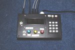
Just to let you know I have now completed the controller and all is working as planned.
I will get a few images to show the unit and attached equipment when my PC is back up and running. Then it is setting up in anger and get some decent action shots to show you all.
A big thank you to all who have helped along the way, without your help I would still be sat scratching my head working it all out.
Stewart
I've not been keepingup with this thread, but surely it is a short upgrade from controlling a water droplet to this...
http://www.youtube.com/watch?v=UdZyrZWAUZg&feature=related
http://www.youtube.com/watch?v=UdZyrZWAUZg&feature=related
bfgstew
Senior Member
Hi all
Sorry for abscence but been on hols and been poorly for a few weeks, so thought it polite to post an update on my project.
It is completed and works, but, as all projects, after completion you find a few things that 'could' have been done better.
Well this is what I have found...................
The sound trigger is a bit iffy, very difficult to adjust and needs a lot of noise to trigger it, so a Mark II is being drawn up at the moment using a LM386 Opamp, so should cure that.
I'm still not happy with the flash and camera trigger timings, they do the job as it is, but need it to be more accurate and from a set datum point in the code, so need to re write the code accordingly.
I am in the throws of using Design spark to get a PCB made for it, so the box will need a bit of cosmetics on it, make it a bit more streamlined and the layout more user friendly.
Apart from that, all is going well with it. In the next few months it should get used in anger and will post the results for all to see.
A big thanks to all those who have helped during the build, much appreciated.
Stewart
Hi Stewart,
I have just seen your project update and pleased that it was successful, I have just finished construction of a camera trigger using a 20x2, it has several functions one of which is for water drops which i have had a lot of fun with so far. The light/sound sensor input is self adjusting for ambient levels and will successfully trigger on the light from a flash unit when fired in the vicinity, in daylight to simulate a lightning event (in daylight). I have only just started to place documentation on my site but hope to have circuits and code up there soon. i have attached a couple of shots i have taken with my water drops setup.


Regards Mike,
http://codenquilts.com.au
I have just seen your project update and pleased that it was successful, I have just finished construction of a camera trigger using a 20x2, it has several functions one of which is for water drops which i have had a lot of fun with so far. The light/sound sensor input is self adjusting for ambient levels and will successfully trigger on the light from a flash unit when fired in the vicinity, in daylight to simulate a lightning event (in daylight). I have only just started to place documentation on my site but hope to have circuits and code up there soon. i have attached a couple of shots i have taken with my water drops setup.
Regards Mike,
http://codenquilts.com.au
bfgstew
Senior Member
A nice looking unit Mark, thanks for sharing your project and shots, very nice.
The light trigger was an option I thought about but didn't have enough pins on the 20M chip! But as I am on the Mk3 version I may upgrade to a 28M chip and add to the function list. The hard part is getting it all into one box, small enough to carry and have the ability to run on either mains so it fine in studio or battery pack so it could be used 'in the field'.
Also I am making my own PCB processing kit so I can move away from variboard and as upgrading again, circuit schematics and coding are changing so when all is done will post. Will keep an eye on your website for updates also.
Stewart
bfgstew
Senior Member
After a lot of reworking and a few additions, I have completed testing all the outputs of the control box and all works well.
Now to alter the PCB's then I can get them made and build the unit up. I can see light at the end of the tunnel...................
Cheers to all who have helped along the way, much appreciated.
Stewart
Now to alter the PCB's then I can get them made and build the unit up. I can see light at the end of the tunnel...................
Cheers to all who have helped along the way, much appreciated.
Stewart
bfgstew
Senior Member
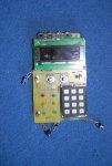
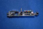
Ok a quick update, PCB's desigend, etched and built up, unit assembled just as a chassis until I can shoe horn it into its box.
All 4 code slots uploaded and so far initial trials are going ok, now need to do some proper hardware tests to make sure the output and inputs are doing what they are supposed to do.
I did manage to get 4 solenoids into my design which was brilliant, I used the spare I/O's off the OLED driver chip, i had to set them on a seperate board stacked on top of the other outputs under the OLED, but it works well.
Only thing I need to alter is the height of the middle board to suit the box lid but that is a minor alteration.
Updates will come as I progress, thanks once again for all those who have helped.
Stewart
bfgstew
Senior Member
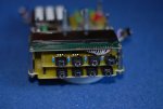
Another update on the controller, all built and testing is coming on nicely, albeit slowly.
All 4 solenoids work, the photogate has taken a different guise and is now a laser gate which works perfectly, camera and flash outputs are spot on, just the sound and light inputs to test now.
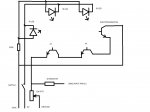
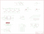
BUT, I have come across a problem. The 28X2 developed a fault - I couldn't get numbers 4 to 9 work on the keypad, after a lot of checking I found the chip to be at fault? So replaced it with my spare and all was well until the other day and it happened again? I cannot figure out how and why this is happening, i put both chips on the AXE 091 board and set up to run all pins as outputs to flash an LED and found a couple of pins either stuck as outputs or not working at all. I have attached a schematic of the controller, hopefully it is readable and easy to understand, any ideas on this problem would be gratefully recieved.
Running from a 12VDC wall plug unit.
All 4 solenoids work, the photogate has taken a different guise and is now a laser gate which works perfectly, camera and flash outputs are spot on, just the sound and light inputs to test now.
BUT, I have come across a problem. The 28X2 developed a fault - I couldn't get numbers 4 to 9 work on the keypad, after a lot of checking I found the chip to be at fault? So replaced it with my spare and all was well until the other day and it happened again? I cannot figure out how and why this is happening, i put both chips on the AXE 091 board and set up to run all pins as outputs to flash an LED and found a couple of pins either stuck as outputs or not working at all. I have attached a schematic of the controller, hopefully it is readable and easy to understand, any ideas on this problem would be gratefully recieved.
Running from a 12VDC wall plug unit.
I'm having resolution trouble , some text is blobby - your keyboard matrix looks joined to the OLED (the B.x lables)?
Can you check and do a higher res image?
Assuming it is connected correctly really, is there a chance in your code that a strobing output can be connected (via keypress) to a pin not set as an input? Sometimes code can cock up good hardware.
Can you check and do a higher res image?
Assuming it is connected correctly really, is there a chance in your code that a strobing output can be connected (via keypress) to a pin not set as an input? Sometimes code can cock up good hardware.
bfgstew
Senior Member
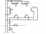
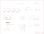
Is this better Dippy?
PCB layout as well. I have ommited the keypad and OLED screen for clarity but should see how and where they are connected.
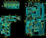
I'm afraid that's the best I can upload, keep getting error message if I go any bigger???
Keypad is connected OK, the only things connected to the OLED are 3 LED's and of course the OLED itself. It is strange as it worked fine for days and days whilst testing, then it just stops,
PCB layout as well. I have ommited the keypad and OLED screen for clarity but should see how and where they are connected.
I'm afraid that's the best I can upload, keep getting error message if I go any bigger???
Keypad is connected OK, the only things connected to the OLED are 3 LED's and of course the OLED itself. It is strange as it worked fine for days and days whilst testing, then it just stops,
Attachments
-
 60.1 KB Views: 11
Last edited: