Counting, frequency, Jeremy Leach

hippy

Ex-Staff (retired)
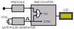
The diagram makes it clear and the 08M is redundant. The simple setup is as in the attachment.

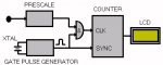
There are two options for the pulse generation; let it free-run and synchronise to it ( as in attached ) or tell the generator to give a gating pulse when the counter is ready to start counting. That's probably better and easier to code.

On choice of crystal it doesn't really matter as long as you can generate a pulse of a length which makes the counter maths easy; 20ms = x 50, 25ms = x 40, 1000ms = x 1. The longer the better, the more accurate. Peculiar value crystals may cause a problem ( internal clock of 66.6666666ns etc ) but others, divided by powers of two may make things easier - 4.194304 MHz divided by 2^22 = 1s. If using a PICAXE to generate the pulse, the limited length of on-chip hardware dividers ( via counters ) is why a slower crystal is probably best.
 

Attachments

hippy

Ex-Staff (retired)
One PICAXE worth looking at for the counter is the 18M2, with reference to the 16F1827 datasheet (figure 20-1) Timer 1 has Gate Control built-in which would likely save the external AND gate. I'm sure the 18M2 would have enough speed at 32MHz to keep the MSB's of the 32-bit counter correct. Characteristics seem the same as the others, up to 16MHz clock rate allowed.
 

Attachments

Last edited:

hippy

Ex-Staff (retired)
After a long slog, lots of banging of head on desk and reading datasheets repeatedly I just cannot get a 28X2-5V to generate an accurate width pulse.

Code attached. This uses on-chip hardware entirely so should 'just work'. At EM32 with 8MHz resonator that should be Fosc=8MHz. Clock TMR3 from Fosc through a divide by 8 pre-scaler and TMR3 should increment every microsecond. Set CCP1 and CCP2 to trigger when TMR3 hits 50000 and both should trigger when 50000us have elapsed, 50ms. CCP1 is used to toggle output C.2, CCP2 is used to reset TMR3 to zero.

That all works, or nearly. High pulse is 49.967688ms, low pulse is 49.967813ms. It's not uncommon for on-chip hardware to be different in high and low periods but the sum is then usually correct. In this case not. Also tweaking the 50000 in CCP1 and CCP2 doesn't seem to alter things as would be expected.

Even using "PWMOUT C.2, 16, 32" throws up some anomalies; most high pulses are 1000ns, but occasionally 958ns. Most lows are 1125ns but occasionally 1167ns and 1083ns and not occurring with the iffy highs.

So either I've not got things right, the PICAXE firmware is interfering, it's PLL jitter, or the logic analyser isn't always telling the truth. Maybe someone else can make a good guess as to why it's not working.

Current conclusion is that gating pulse generation would best be done by a hardware divider from a crystal source.

I did at one point have a 28X2 generating a close to 50ms pulse plus a 4MHz reference for testing the counter with but it got lost in the editing. I'll recreate that later as it will still be useful to have.

Added: There's a few typos in the source code.

Also, using TMR3 free-running, CCP1 toggling C.2 on match, it should be toggling every 65536us; every 65475.9us according to the analyser. Something very weird going on.
 

Attachments

Last edited:

nbw

Senior Member
OK, the 08M is out of the window. I haven't managed to get my hands on an 18M2 yet, I did look at them initially as the four parallel program flows sounded useful for this app. I"m wondering now if it might be better to turn things around a bit. Have the 40x2 chip running on a 16 or 32MHz (I have the latter already ordered but could track down a 16. I have a 6.00000 MHz crystal also as I mentioned earlier.). Then, I have a 20x2 which should be adequate to do the counting (the easy bit). The 40x2 could still do the display via the max7219 - as it wouldn't be timing and displaying the same time.

I wonder if the resonator Hippy just isn't accurate enough and there's a little variation creeping in there? Crystals are by all accounts a couple of magnitudes more accurate.
I can see that the crystal is going to be a must-have. That immediately restricts some picaxes that can't use external timing sources.

My experience with PLL is very limited, my understanding that timing with PLL was as tight as two coats of paint in terms of accuracy.

My mother-in-law lives in England and Christmas present time is coming up, so if the 18M2 is a real option I could send her an email.

In your top digram Hippy I see the layout now, as you say the 08M is unnecessary; the picaxe doing the timing has a PWMOUT going non-stop, the one doing the display / counting can handle the rest.
 

Dippy

Moderator
I haven't followed this intricate thread, but will just say a couple of things;
1. If you want accuracy and stability then crystal is the only way.
2. In the World of PICs PLLing is often scoffed at with regards accuracy; it appears to amplify the clock errors.
I have also 'suffered' with PLL problems, I would never use it where timing is important. I've seen numerous 'negative' mentions on various professional Forums.
 

hippy

Ex-Staff (retired)
I agree with crystal for best accuracy but a resonator shouldn't be too far out; the discrepancies I'm seeing are much larger than resonator errors would be. I'm seeing similar issues with 28X1 which doesn't have a PLL.

I honestly don't know what the issue is and don't intend to pursue that, though I'm sure it will keep nagging at me as to why. I can only conclude a PICAXE for gating pulse generation isn't the way forward at this time. Apart from a hardware divider from crystal, a PICmicro using a crystal would be my choice, use NOP's for timing.

What is bugging me now is how accurate counting will be; will there be any unexpected glitches in that ? It can only be assessed with a counter built, an accurate gating pulse and a reference frequency generator and I don't have either of the latter.

One could go to a hardware 32-bit counter and have the PICAXE read that which would be simple and work. In fact, all we're doing is taking a hardware solution and using on-chip peripherals and software to cut down component count so going the other way to overcome silicon and software issues isn't 'offensive' nor wrong per se.

It's also fair to say that I'm aiming for 0% error with best accuracy possible and the PICAXE is perfectly capable of doing the job if one is prepared to accept greater inaccuracy or invest the time in overcoming whatever the problem is. Getting the PICAXE to do what I wanted took minutes, fine-tuning has taken hours and still isn't there. I can still see that as more of a success for PICAXE than failure, and it's by no means certain the problem lies with the PICAXE itself.

I'll still port the counting code to an 18M2 to take advantage of the Timer 1 gating and frequency input not being on Serial In to see if that works.
 

Jeremy Leach

Senior Member
Hmm it sounds tricky.
Well it all boils down to working out Pulses/Time. You either fix the Time period and measure the pulses or you measure the time for a fixed number of pulses.

Perhaps your accurate clock idea might be the best idea afterall Hippy? Have a cheap external ripple counter and measure the time for a fixed number of pulses. Then 'somehow' deal with the maths. It's a long time since I messed with my 32bit division routine, but I'm pretty certain it worked ok - so it in theory might be able to translate the result into Pulses per second. It would be overkill (and spoil the challenge) to use a separate floating point processor!

On the PWMout blips - I suppose you could have another crystal driven PICAXE and measure the PWM pulses using pulsin. Sample lots of times (maybe just leave it to run for an hour or so) and then make a histogram of the proportion that are the different widths. Ok, it wouldn't say 'why' the blips occur but it might help to get an accurate picture of the PWM signal.
 

hippy

Ex-Staff (retired)
The big problem in the system, no matter how it's done, is how accurate things are. It becomes pointless to measure gating pulse times etc if the measuring of those is equally suspect.

Not saying alternative approaches are wrong but seem unnecessarily more complicated to me than they need to be, or only necessary because what was hoped for is proving difficult to turn into a practical solution.

We have to face it, that in hardware this is an absolutely simple problem to solve. A counter which counts pulses over a period of time, that count is scaled depending on what the sample time was and displayed as a frequency. Choose a 1 second sample time and there is no scaling. It doesn't often get more simpler than that.

If there's a gated 32-bit counter in a 40-pin DIP which can handle 200MHz+ input frequencies then that's job done other than providing the gating pulse and taking those 32-bits and displaying as a number. It's easy enough to build a 32-bit counter from smaller ones. The DS2423 looked handy as a one-wire(TM) 32-bit counter but isn't in production and hasn't the input frequency capability. Maybe there are some other options along similar lines.

The problem isn't so much in theory or design but in turning it into a workable reality. It should be a very simple thing to solve, but unfortunately, and unexpectedly, is proving it isn't.
 

nbw

Senior Member
*Boom*

I'm really surprised a PICAXE is struggling with this. Maybe the separate IC-crystal to do the timing, and let the PICAXE do the maths as Jeremy suggests. There's no doubt the PICAXEs can handle that, and even 32-bit juggling should be able to be done in a fraction of a second and without too much hassle (unlike dedicated ICs)

Or another option is to have a 4040, a pre-scaler, and a 4060+crystal to generate the timebase off a 3.2768 MHz crystal. This crystal would negate the /2 counting of the 4040, and then the output could be passed to 74390 dual decade counters than can drive 2 digits per IC.

thanks for all of your time spent Hippy.
 
Top