Counting, frequency, Jeremy Leach

nbw

Senior Member
Are you telling me that after all these years of putting toothpaste into the tank, it HASN'T been improving performance?!?!?

Seriously, anything I do with a PICAXE I wear on my own head (metaphorically). I mean, how is Rev-Ed supposed to know what I've done, how I've done, what I've butchered on the way to doing it. When I was a young chap about 20-odd years ago PEEK used to be safe with computers, it was POKE (and VPOKE) that got you into trouble!

It would be handy as Jeremy says, to have a list of 'greyer' areas of interest where the disclaimer is re-iterated, but the experimenter user can have a look if she or he wants. One never knows, someone playing around in these areas might find a bug to fix or a new feature for a later product / version.... :)

ps. good night folks in the NH
 
Last edited:

hippy

Ex-Staff (retired)
It would be nice if some of these PEEKable addresses were published too
If from Rev-Ed, then it becomes 'officially supported' with all the costs, effort and so forth that entails. It's the forever present need to draw a line between what is supported and documented and being all things to all men.

One thing to add is that there has never been any intention by Rev-Ed to limit how PICAXE commands are used If people wish to experiment then they are allowed to do so.
 
Last edited:

Jeremy Leach

Senior Member
I really can't see the problem of giving the info with a disclaimer. Isn't it better to list unsupported methods than not at all, from a product perspective? Luckily I don't need to know the answer for this thread :).
 

westaust55

Moderator
It would be nice if some of these PEEKable addresses were published too, so people can experiment (knowing that discaimer x applies). I'm sure it's all in the low level datasheets for the PICs but I don't see the problem in making the info available (apologies if it's already in the manual somewhere).
My interpretation of the peekable and pokeable SFR locations in the 18M2 chip are attached in post 13 here

This table refects that 18M2 SFR "address" and the details for that location.
There are many more locations that PICAXE BASIC cannot access.
 

Jeremy Leach

Senior Member
Now that's good Westy - I can see the Timers mentioned in there. I guess the address might also depend on the model of PIC.

So nbw, it might be worth experimenting to see if you can Peek this counter value after gating the counter. I can see there are lots of factors to consider though.

One thing you need to know is the maximum frequency the PICAXE Timer/Counter can run at.

And then the autoranging.

And then how to translate a 32 bit (or higher bit) count value into a decimal result. I think this could be easy though, because you could set a prescaler value so the overflow of the counter occured at 10000. Then you would have a decimal value of XXXXXYYYY and could just write it directly to the display.
 

hippy

Ex-Staff (retired)
Code for 32-bit ( and larger ) to decimal is easy enough ...

http://www.picaxeforum.co.uk/showpost.php?p=127083&postcount=7

It's then just a question of catching overflows, incrementing higher order bytes / words.

For an input frequency higher than the counter can handle it will need external division; power-of-two is best as that makes the multiplication of larger than 16-bit numbers simple shift operations.
 

hippy

Ex-Staff (retired)
32-bits is good enough for 4GHz to 10 digit accuracy, so that covers 200MHz to 9 digit accuracy. Assuming a max PICAXE input frequency to the counter of 2MHz, that would need a divide by 100 in front, which would give 7 digits of accuracy which appears to meet the requirements.

It seems the PICAXE input is good for 10MHz, so divide by 20.

Forget what I said earlier about dividing by power-of-two as divide by 10 doesn't need any complicated multiplication fixup, just add zeroes on the end of the display!

At 10MHz the internal 16-bit timer will overflow every 6553.6us, so you need to check overflow and increment the upper 32-bits of the counter within 6.5ms. That should be achievable with a 20X2 at 64MHz and possible at lower frequencies. It should also be enough time to check the gated frequency is incrementing the counter, to automatically finish when it does not.

You'd therefore need to provide a divide by 20, a gate to let your frequency pulses through, take the readings, multiply by 2 and display the results with a zero added. You'd need an accurate gating pulse of exactly one second to achieve maximum accuracy.

The easiest way may be to use a crystal oscillator, divide that down to 2Hz, or 1Hz and measure frequency for half a second, multiply by two in software.

I'd start with either PWMOUT or an up to 10MHz ( maybe 12MHz ) crystal module and routing the pulses through a switch held for a second, just to get the basics working without worrying about accuracy.
 
Last edited:

Jeremy Leach

Senior Member
At 10MHz the internal 16-bit timer will overflow every 6553.6us, so you need to check overflow and increment the upper 32-bits of the counter within 6.5ms.
This is where I might be getting confused. I thought the PICAXE has a special, predefined, Timer variable that is automatically incremented on this overflow and can be used directly in code? So there's no need to get the code to check for overflow.

From the manual under 'SetTimer'
When the internal
counter register overflows from 65535 to 0, the special ‘timer’ variable is
automatically incremented.
Therefore to increment the timer variable on every 10 external pulses set the
preload value to 65536 - 10 = 65526. After ten pulses the counter register will
overflow and hence increment the ‘timer’ variable. To increment the ‘timer’

variable on every external pulse simply set the preload value to 65535.
If possible I still think it would be easier (for display purposes) to load a preload value so the overflow is at 10000 and not 65536.
 
Last edited:

hippy

Ex-Staff (retired)
Yes, you probably could use the internal interrupt handler and the 'timer' variable. I also meant the upper 16-bits ( not 32 ).

The main reason I did not use those is I already had code which used the timer SFR's direct.
 

hippy

Ex-Staff (retired)
Attached is example code for reading frequencies which seems good to 8MHz. Haven't got a frequency generator to hand nor any oscillator modules so cannot test higher.

It's not accurate; uses 8MHz generated via PWMOUT and requires holding the button for precisely one second - Assuming the PICAXE clock speed is smack on, the button held for exactly one second it should show "0008000000 Hz / 0008.000000 MHz".
 

Attachments

nbw

Senior Member
crumbs, I'm going to need a beer or two while I get to grips with that code. What I can do to kick the process off is:

1. confirm the picaxe - it will be a 40X2 (I found one in the shed). I have a 20X2 and although this can run faster, it's internal. The 40X2 will run off an external crystal (32MHz). This should hopefully give reasonable accuracy compared to a PWMOUT clock.
2. build the hardware side of things. It will use a MC12080 prescaler which can divide by 10, 20, 40, or 80.
3. I may not need by the sounds of it a 74HC4040 hi-speed 12-bit counter, but I have one available to use downstream from the MC12080 if required. This can run at around 30MHz, so even with the 12080 at /20, this would cater for 0.6 GHz.
4. The 12080 outputs a square wave from its D F-Flops, ( 0 - 1.2V) so a simple voltage amplifier will raise it to 5 - 0.7V = 4.3V. A bog-standard PN100 NPN transistor has a min switching frequency of 250MHz so should be able to handle anything the 12080 throws at it.
5. Autoranging - I'll build this in once I have the 80 - 100MHz working ok.
6. Display - I'll use the sertxd for now while getting the thing working. Ultimately I'll connect up 8 x 4543 BCD drivers as 1, I'm old-school and like 7-seg displays 2, I have a dozen odd of these kicking around and 3, the 40x2 has tons of outputs :)

thanks for your suggestions etc everyone, I find them helpful and am (slowly) learning.
 

Jeremy Leach

Senior Member
Here's my line of thinking ...

You want to measure up to 200MHz.

If the PICAXE can handle up to 10MHz on the internal 16-bit timer, then need divide-by-20 stage before the timer.

So looking at the maths straight away:
Freq = CountsPerSecond * 20

I think it might be a good idea to sample the frequency using Pulsout, because it might be the most accurate method, rather than relying on any code to trigger the start/stop of the sampling. Perhaps use a diode AND gate to achieve the gating using this pulsout as one input, and the raw dived-by-20 signal as the other input.

With a PICAXE clock of 32MHz, Pulsout pin,40000 will give a pulse of 40000*1.25us = 50ms. So if we executed 4 Pulsouts in a row then the total sample time would be 200ms, or a fifth of a second.

Freq = (CountsPerFifthSecond * 5)* 20 = CountsPerFifthSecond * 100

For a measured frequency of 200MHz, 10Mz would hit the PICAXE, the counts received in 200ms will be 2,000,000. If we load the Timer with a preload value of 55536 then the counter will overflow every 10000 counts and increment the Timer variable. So 2,000,000 counts will mean that the Timer variable will hold 200 and the internal Counter will hold 0.

If the measured frequency was 199.1234 MHz then the Timer variable would hold 199 and the internal counter would hold 1234.

Rough code ...
Code:
Do
'Reset counter
Timer = 0
SetTimer ... 'Set it to count mode, with a preload of 55536
 
'Sample incoming pulse stream
For i = 1 to 4
    Pulseout Pin,40000
Next
 
'Read the result
Peek CounterAddress, CounterValue
 
'Display the result
Serout ... Timer,".", CounterValue
Loop
 
Last edited:

hippy

Ex-Staff (retired)
I've remembered my other wariness of using SETTIMER - The timer overflows, interrupts, then the preload value is loaded. There will be some delay between overflow and being reset to preload value, counts will be lost.

We are talking mere microsecond losses or less which in most cases won't have a material effect ( and often no effect ) on the application but when needing accuracy and have a high-speed incoming clock a free-running, never altered, counter / timer is best.

It may be possible to tweak the preload value to compensate for losses, so the idea isn't completely unworkable, but that's extra effort. The SETTIMER method would be an easier and suitable method for lower input frequencies.

Having read the datasheet and understood it best I can, it looks like 16.66MHz is the maximum input clocking rate. Looking at other "50MHz frequency meter" projects on Google this seems to match, though some suggest much higher frequencies can be used without external pre-scaler - I suspect that was assumed rather than tested, based on what the software can do, using internal pre-scaler and not what the hardware supports.

I'd settle for 10MHz max to give a bit of leeway, it makes the divide by 20 easy to handle, and should allow up to 320MHz to be read to 7-digit accuracy.
 
Last edited:

hippy

Ex-Staff (retired)
On PULSOUT to generate gating; that has issues. If it cannot be interrupted you will lose timer overflows in that time, if it is interrupted, the period you are timing for becomes extended by the overhead while interrupts are being handled. Not easy to adjust for as the number of interrupts depend on the frequency.

There's also an issue of accuracy; if a PICAXE generates a 100ms PULSOUT pulse, and that's actually 100.001ms then in most cases it will not matter but it can start to add up here. I don't know what the actual accuracy is; it will be better at higher system speeds.
 

MartinM57

Moderator
If the PICAXE can handle up to 10MHz on the internal 16-bit timer, then need divide-by-20 stage before the timer.
Doesn't that instantly bring in an "up to 5%" error possibility on the displayed value - or am I not following the thread closely enough? (which I'm not ;))
 

Jeremy Leach

Senior Member
Hi Martin : I know, but I think perhaps the app is to measure 'up to' 200MHz, to 7 digit accuracy.

Hippy: Well I wasn't thinking of using interrupts at all, if the Timer variable is automatically incremented. The manual seems to indicate that Pulseout is to 1.25us resolution at 32MHz clock.

I don't know, it's all down to nbw and what he needs :). There are a few ideas here to try out.
 

hippy

Ex-Staff (retired)
@ MartinM57 : Not quite. We can measure 10MHz to 1Hz accuracy, with a divide by 20 that's measuring 200MHz to 20Hz accuracy.

@ Jeremy : It's not PICAXE program interrupts, but internal hardware interrupts the firmware uses to increment the 'timer' variable.

I agree it's mainly in nbw's hands now. We've proven a 20X2 can read 8MHz to 1Hz accuracy and most likely 10MHz to 1Hz accuracy, it's now a question of ensuring gating is of the right duration, adding prescaler and adjusting reading to compensate for the prescaling, plus whatever output formatting and display is required.
 

Jeremy Leach

Senior Member
Ok, I understand what you're saying Hippy.

Here's another idea though:
How about using Pulsin to measure the pulse-width from the outputs of a 4040? Pulsin measures to 1.25us @ 32MHz PICAXE clock. If Timeout occurs the result is 0. Have multiples connections between 4040 output pins and PICAXE input pins.

Autorange to select the best pin to Pulsin on: Pulsin on the 'slowest' pins first (ie the higher divisions). If timeout occurs then select the next pin down. Iterate until a non-zero Pulsin result.

Then the PICAXE does the maths.

I 'think' the formula for freq would be (for 32MHz PICAXE):
F= 400,000 * D/P (D = Division of 4040, P = the Pulsin returned value)
Which is a nasty calculation but might be possible using 32-bit maths.

It's a bit of a wierd solution though, because it's measuring a divided down pulse.
 

hippy

Ex-Staff (retired)
Agreed, that should work ( read high and low pulse for non-50% duty input ) but the maths gets a bit hairy ( for me at least ). IMO it's just easier to read a 32-bit counter, the number you want which is all I am doing despite the apparent complexity of the software.

A further thought is: with counting done on a 28X2 with crystal, counter moved to timer3, it may be possible to generate a hardware gating signal which is derived from the crystal using the other three timers, CCP mode or similar. Might investigate that later.
 

hippy

Ex-Staff (retired)
Couldn't get Timer3 to work as per Timer1 on the 20X2, but it does appear Timer3 can be used to generate gating pulses. This seems to generate 25ms pulses or there abouts as it's not crystal controlled


Code:
  SetFreq M64
  
  T3RD16_BIT  = 0 ' Read as 8-bit timer parts
  T3CKPS1_BIT = 1 ' Divide by 8 Pre-Scaler
  T3CKPS0_BIT = 1 ' Divide by 8 Pre-Scaler
  T3CCP1_BIT  = 1 ' Timer 3 drives ECCP1 capture/compare
  T3SYNC_BIT  = 1 ' Synchronise Clock
  TMR3CS_BIT  = 0 ' Internal Clock
  TMR3ON_BIT  = 1 ' Timer 3 Enabled

  PokeSfr T3CON, b0

  P1M1_BIT   = 0 ' Not used
  P1M0_BIT   = 0
  DC1B1_BIT  = 0 ' Not used
  DC1B0_BIT  = 0
  CCP1M3_BIT = 0 ' Compare mode, toggle on match
  CCP1M2_BIT = 0
  CCP1M1_BIT = 1
  CCP1M0_BIT = 0

  PokeSfr CCP1CON, b0

  dirsC.5 = 1

  Do
    PeekSfr PIR1, b0
    If CCP1IF_BIT = 1 Then
      CCP1IF_BIT = 0
      PokeSfr PIR1, b0
      PeekSfr CCP1L, b0
      PeekSfr CCP1H, b1
      w0 = w0 + 50000
      PokeSfr CCP1L, b0
      PokeSfr CCP1H, b1
    End If
  Loop
 

Jeremy Leach

Senior Member
I have thought of another wacky idea: Generate a known frequency square wave with PWM, mix it with the incoming signal (diode AND gate?) and then measure the beat frequency (AND gate > Buffer > RC smoothing > Scmidtt Counter Input). IF this worked then would have advantage of lower frequency to measure, plus perhaps a range of PWM frequencies to send.

Not saying it would work though !
 

Dippy

Moderator
Ooh Jeremy, I think you'll open up a massive can of harmonics with that one ... :eek:

Prepare yourself for the deluge. Good luck ;)

If I were you I'd go back and change it to: "Do you remember that frequency counter in the 1993 Maplin Magazine?"
 

Jeremy Leach

Senior Member
Ha, ok I'll not mention it :).

I'm just not sure if would work anyway. I know there are heterodyne frequency counters out there, but they use Sine waves. Probably for a good reason !
 

nbw

Senior Member
Crumbs, my head's starting to hurt now.

I've pretty much decided on the hardware. If I've understood the general gist, a 40x2 will be fine, a 32MHz crystal will be pretty accurate compared to getting the picaxe to generate PULSOUTs, the 32-bit convert to BCD code is great (thanks Hippy), and 7 digits resolution is doable. I'd be happy with 100MHz going down to 100Hz.

So the hardware will consist of a 40x2 @ 32MHz, and I prefer the idea of counting for an uninterrupted period, then doing some "simple" 32-bit transmogrification at the end. Hippy's post above #59 seems to be heading in this path. Is the consensus that I'll still need a 4040 in there? I'm also assuming I need the 12080 pre-scaler.

I thought I'd restate what I'm trying to achieve:
(up to 200MHz, 500 would be nicer - to check 433 MHz modules :)

Display:
200,123,456 Hz --> 200.1234 MHz (show as)
3,123,456 Hz -- > 3.123456 MHz
524,789 Hz --> 524.789 kHz
2,891 Hz --> 2,891 Hz

Gate time:
happy to have it anywhere up to 1 or 2 seconds if required. This should be controlled by the picaxe, ideally.

Pre-scaler:
MC12080 which can divide up to 1.1GHz by /10, /20, /40, /80 as required

Auto-ranging:
should be able to do that via the picaxe code. Alternative is to have a rotary switch which would select up to 500MHz, up to 100, 50, 5, 1, 0.5MHz, 0.1 etc

I'm very grateful for your thoughts and suggestions so far.

cheers
Barney
 

nbw

Senior Member
Added:
The pre-scaler will be set up to divide by 80. I like the sound of the SETTIMER. With the /80 of the pre-scaler, a 100MHz signal would be dropped to 1.25MHz, which you would think a 40x2 would eat for breakfast. The /80 is a multiple of Hippy's suggested /20, which helps.

A thought: one might be able to compensate for the tiny delay as the interrupt overflows. For example, if it overflowed 8 times in the count, and you know it takes 1us to overflow, you could add / adjust that to the count.

Thought2: originally I had the 4040 in there because I was going to use COUNT, which would be good for up to 200 kHz tops. With a /80 prescaler, and the turbo-charged 40x2, I won't need it at all I believe. Even at 500 MHz, only 6.25 MHz would be hitting the picaxe.
 

nbw

Senior Member
I've just been reading up a bit on SETTIMER. In external mode on pin C.0, if it overflows it sets toflag (timer overflow flag). The manual then goes on to say 'setintflags' can be set to manually trap the overflow. I was thinking this could be useful but of course - an interrupt is going to cause more delays....

But the main thought would be to, on each overflow, perhaps increment a variable or memory address that I could read after the gate, to work out the full number of counts.
 
Last edited:

nbw

Senior Member
On a related note, I've also been giving some thought to displays. From one of my other projects, I used a MAX7219 that drove 8 x 7-seg displays. I should probably re-use that rather than chaining a pile of 4026s together. It worked really well (I think Martin nutted out the main code for communicating with that IC). Very easy to operate, and I'm thinking with Hippy's 32-bit double word code, the resulting BCD number would be a piece of cake to slice and distribute to the relevant digitry.

Also - for controlling the three H/L pins on the pre-scaler, I thought a natty old 4066 analog switch IC I found in the shed would be ideal for sending the necessary High / Low signals to the other IC, for determining whether it's to scale down by a factor of 10, 20, 40, 80. These analog switches typically have a relatively high on resistance of around 100 ohms, but I doubt that will upset the pre-scaler - it probably only needs a mA or so on these pins.
 

Jeremy Leach

Senior Member
SETTIMER:
Hippy has pointed out that the firmware generates an internal interrupt (not a user-visible interrupt) to increment the Timer variable when the counter overflows and the execution of this interrupt would cause some counts to be missed.

In theory it might be possible to work out (via tests) the duration of this interrupt routine (assuming it was constant) and then try to compensate for the lost counts. Either by:
1) taking the duration of the interrupts out of the sample time. However adjusting the sample time might make the later maths horrible.
2) making an estimate of the number of missed counts. However you'd need to know the frequency to estimate the missed counts !
The number of interrupts would be easy - it's just the value of the Timer variable.

PRE-SCALER
Well 200MHz needs to reduce to 10MHhz for the PICAXE to be able to read it. To me, the choice of pre-scalers goes hand in hand with the rest of the solution, because the maths can be made much easier with the right prescalers.

I think it would be nice to have an automatic selection of prescaler if possible, so you can choose the one that will give the most accurate result for the frequency being measured.

AUTO-RANGING
That's just playing with the digits in code, so I don't think you need to worry about that at this stage.
 

hippy

Ex-Staff (retired)
I'd personally recommend against SETTIMER and other potential tricks and just use a 32-bit counter as in my code but if you want to try it do so. Set up a prototype to see how it works; get a crystal controlled PICAXE generating 8MHz or 4MHz and see if the results look right. You don't need the external pre-scaler.

For the final system, you just need the external pre-scaler not any 4040's and you don't need any 4066 for selecting division; just drive from PICAXE legs direct.

A divide by 80 pre-scaler will be good for up to 1.2GHz. Doesn't really matter what pre-scale you use as long as PICAXE Input frequency is ~10MHz. It only affects the accuracy of the display; 1.2GHz should be accurate to 80Hz.

Generating a gating pulse could be possible on the single PICAXE also reading the frequency but I'd have a separate crystal contolled PICAXE generate that. The frequency reading PICAXE doesn't need to be crystal controlled in that case.

Otherwise there's a conflict in requirements; frequency reading PICAXE should be fast as possible, gating generator slow as possible to generate longest pulses. Or use crystal and a hardware divider to generate the gating pulses as described earlier, no PICAXE needed.

Time to start prototyping; get a 10MHz frequency meter working first.
 

nbw

Senior Member
Yes indeed. The 12080 will be arriving in the next day or so. The 4040 and 4066 are back in the box. It would be nice to have a single picaxe, the 40x2, running the whole show but I do have the following picaxes available (spare-ish - so could be used to generate the gate):

18X - good for 8MHz, but not with external crystal
20X - good for 64MHz, but as per 18X (not external)
40X - good for 16MHz, but I only have a 4 and 32MHz crystal (I have a 16MHz resonator though)
28X1 - good for up to 20MHz, but I only have a 4M crystal / 16M resonator... and it seems a bit of a waste to use this beautiful beast simply to make a gate

We have a long weekend coming up with a public holiday, so I might make a rudimentary PCB with the 40x2, pre-scaler etc all very close together and try out your code Hippy in post #50 above. I'm sure I've missed something obvious in there, but I'm not sure how to get it to run for (as close as possible) to one second, beyond adding a pushbutton and operating the 'Waitforcounter' routines using that? Either that or do something like 'pause 999' to get it to wait about 1 second? (maybe I'll need to prototype using 2 picaxes)
 

hippy

Ex-Staff (retired)
My code will automatically run, start and stop. Remove the button, add an AND gate into Serial In (T13CKI), the AND gate driven from a 0.5Hz clock (gating) and the signal you want to measure the frequency of, simple as that.

It prepares the counter, then waits until it sees it counting, waits until it's stopped counting ( so only counts when the gate is present ), then calculates the results and displays them, then repeats.

The 'bug' is that it doesn't synchronise to preparing the counter before the gating pulse is present, but should work if the calculation and display takes less than a second. First ever reading may be wrong.

Should be easy enough to fix that and I've got updated code for pre-scale handling attached; I'll look to add synchronisation to gating later ( basically wait until gate is high, then has gone low ).

It is possible to provide gating and counting on a single PICAXE but code gets complicated compared to using a second PICAXE. Haven't tried with AND gate and fudging it with diode mixing ( gate pulse high forces input to high so prevents counting ) didn't work so well, probably because 8MHz on breadboard with all that stray capacitance.

Because the single chip has to run fast ( to catch freq count overflows every 6.5ms ) its gating pulses are short ( 65536 x pre-scale x clock period / 2 ); 25ms at 64MHz. One can either sample 40 times or less and scale ( with corresponding loss of accuracy ). Bolting that on with current 'end of counting' detection requires a redesign.

A second 'bug' is that it currently thinks the counter has stopped counting for low Hz. Not exactly sure at what point. That would be fixed if using the gate signal rather then doing 'auto-end'.

It's easy enough to change but it's having three PICAXE - counting, gating and generating a reference clock to measure - plus hardware which makes it more complicated to set up. Besides; if I did it all you'd have hardly any project left :)
 

Attachments

nbw

Senior Member
Yes, I definitely want to build as much as possible, but am grateful for the experience you guys have along the way.

I'll knock up a circuit diagram this weekend in Diptrace and post it here for your comments, while I wait for my MC12080s and 32MHz crystal to arrive. That way I can cover off that I have the necessary things like 50ohm impedance matching etc covered off before I launch into the PCB.

The code's the easy bit, right??!

:)
 

nbw

Senior Member
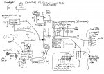
Well, I drew the diagram before the weekend. Not in any fancy software, I thought I'd sketch it out first.

The input is a coax BNC arrangement, with 50 ohm impedance matching. I have also included a pair of back-to-back signal diodes for clipping if required.

We have the 40x2 in the centre - no crystal needed now as it's not going to be generating the timing nor gate, just counting. So it can run at 4 or 8 MHz.

There's the 28x1 generating the clock, initially I thought working off a 16MHz resonator (I don't have a 16MHz crystal). I understand it can go to 20MHz, but the picaxe software editor doesn't support this? I would generate a 10MHz PWMOUT signal. I don't think the 16MHz resonator will be accurate enough. Even the 20x2 internal 64MHz, perhaps won't cut it So, committing to crystal, I'll have to get one. The config is fairly easy as I understand; a couple of caps will be needed.

The prescaler is controlled by the 40x2. A user can select a rotary switch which divide by 10,20,40, or 80 - or not at all. Not sure how to do this as the raw signal would somehow have to bypass the pre-scaler, amplified to make sure it was 0-5V, and then passed to the picaxe. A 100MHz signal at say /20 is going to appear as 5MHz

The 74HC7408 would AND the 28x1 10MHz together and pass it to the timer pin C.0 on the 40X2. I chose a 7408 as it's HC and has very short propagation and transition times (~5ns) versus my 4081 (~100ns), with a max frequency of a couple of MHz. In theory I could crank up the voltage to speed it up towards 10MHz, then I'd need to amplify the signal a bit more etc... probably easier to just get a 7408 that runs around 25+MHz.

Then, it's a matter of getting the little 08M to generate a gate of say 0.5s. It would have been nice to use one of the other picaxes in the arrangement (above), but perhaps an 08M running at 8MHz will generate an accurate enough 0.5s? Your thoughts here would be good. It seems a little wasteful to use another 28x1 or 20x2 for this, if an 08M will do the trick. I half wondered if I couldn't generate a very accurate clock using logic gates etc, but then if I wanted to play around with the timing, that would be a lot more difficult than were it on a picaxe. Speaking of which, the diagram shows the timing controlled by the 40x2, it would in fact be the 08M. There's nothing else for the 08M to do, aside from the RESET (start counting) button.

Other thoughts / ideas you might want to comment on:

1. I've included 1K resistors from the 40x2 to the prescaler, to limit current. The 12080 might be high enough impedance I might to make these unnecessary. Easy enough to include them though.
2. I thought it might be useful (and easy) to have rotary switches that offered no or different pre-scaling, and up to 12 different gate times.
3. I've added 6 LEDs to indicate overange, prescaler is on or off, in auto-range mode, "busy" mode i.e. counting, and 2 to indicate whether the display is in MHz or kHz.
4. There could be an Auto-range button that when off could allow the user to select a number of pre-defined maximum ranges, e.g. 500, 100, 50, 10, 1 MHz, 500kHz, etc. Or, perhaps it would be able to auto-range so fast it wouldn't be worth doing this.

5. For the AND gate, and the picaxes - any unused inputs / outputs I was going to tie to ground.

I (we!) are making progress! Thank you for all your thoughts. Much appreciated.
 
Last edited:

nbw

Senior Member
Out of interest and while I'm waiting for the crystals I've ordered, I rummaged through to see what ones I have. I have 3: 4.782720 MHz, 4.433619 MHz, and 6.000000 MHz. However I figure these (particularly the 1st two) would make the maths a lot nastier than it needs to be, so I'll wait on the crystal front. :)
 

hippy

Ex-Staff (retired)
It seems a diagram is missing if you intended to include it.

I'm not sure where the 08M comes into things, generating the gate pulse; what is the 28X1 doing ? Probably obvious in the diagram.

The fundamental flaw with an 08M generating gating pulse is that it's only accurate to +/-2%, you could perhaps tweak it better that that, but any inaccuracy is going to be reflected in the gating pulse generated. If you have a gating pulse +/-1% that means the period you are sampling is +/-1%, the accuracy of reading is +/-1%. You've reduced the counter instantly to just two-digit accuracy at best.

In fact, the only absolutely critical timing element in the scheme is te gating pulse !

Not sure you need so many options for pre-scale selection. The PICAXE is accurate to 1Hz up to 10MHz and accurate to 20Hz at 200MHz; the only thing you may need to avoid is 10MHz and lower being only accurate to 20Hz, and that may not actually be a problem. I'd have thought a pre-scaler on/off would be enough, select between 20Hz and 1Hz accuracy. Perhaps three options - accurate to 80Hz (1.2GHz max), 20Hz (200MHz max) and 1Hz (10MHz max).

For bypassing the pre-scaler, an AND-OR ( a multiplex ) will probably do the job; it too can be controlled by the PICAXE.
 

hippy

Ex-Staff (retired)
Re Post #77 : I think you are going to have to explain what the crystal / clock it creates is for. The meter part itself is a simple counter, runs independently of operating speed and doesn't need crystal control.
 

nbw

Senior Member
There's a diagram attached now, I forgot to add it before. I'll put that down to my old age.

OK, I've probably missed something crucial. I thought the counting / timing / gate functions were best handled by 3 separate picaxes. The one generating the timing would run on a crystal to ensure accuracy, the 08M would time a 1/2 second start-stop burst, the 40x2 would be responsible for counting the ANDed pulses. Rethinking that though, I guess the 28x1 should be able to manage a 0.5 burst perfectly well (and accurately) without the 08m at all.

You're right I think about the pre-scale options. Even simpler might be just a /80 and /10 option, that way the pre-scaler is always in action and no extra fancies needed there.

So as per the diagram, the 40x2 doing the counting doesn't need to be crystal-controlled, and I've got that running at 8MHz, could do 16MHz. The 28x1 needs to be super-accurate as it's the timer, it's going to need a crystal to achieve that accuracy. So now I'm thinking about what value crystal I'll need, and I was wondering about that 6MHz one I have, or whether it's going to complicate any maths along the way.
 
Top