BillyGreen1973
Senior Member
As some of you may remember, I started thinking about a Serial LCD shield for the Axe401 Shield Base.
I had an idea that it would function just as the Axe033 Serial LCD module does, and use the same commands etc.
Well the easiest way to do that was to use the Axe033 firmware chip to base my shield on. So I did this.
I also kept the onboard DS1307 RTC, as it is useful, and is also in keeping with the Axe033.
I did however decide to take the opertunity to add a couple of extras.
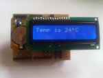
I added an onboard temperature sensor (DS18b20),
I added a pair of I2C headers to allow easier connection of other sensors or I2C modules.
I also added back light control. This is to allow the back light to be ON, OFF or anywhere inbetween using the HWPM command.
This board was my first attempt at using the 'Toner Transfer' method of PCB production, and after a few attempts, found a procedure that works for me.
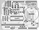
I used Diptrace for the PCB layout, and again this was a learning experience.
As I decided to use only single sided board (I will be doing double sided from now on!) I had to use a few 'link' wires. These are on the layout as 0Ω resistors
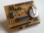
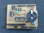
Anyway here it is. There is a bit of a manual available (posted below), that details the parts used, has the board track layout, and a few code examples.
A couple of photos..
I had an idea that it would function just as the Axe033 Serial LCD module does, and use the same commands etc.
Well the easiest way to do that was to use the Axe033 firmware chip to base my shield on. So I did this.
I also kept the onboard DS1307 RTC, as it is useful, and is also in keeping with the Axe033.
I did however decide to take the opertunity to add a couple of extras.
I added an onboard temperature sensor (DS18b20),
I added a pair of I2C headers to allow easier connection of other sensors or I2C modules.
I also added back light control. This is to allow the back light to be ON, OFF or anywhere inbetween using the HWPM command.
This board was my first attempt at using the 'Toner Transfer' method of PCB production, and after a few attempts, found a procedure that works for me.
I used Diptrace for the PCB layout, and again this was a learning experience.
As I decided to use only single sided board (I will be doing double sided from now on!) I had to use a few 'link' wires. These are on the layout as 0Ω resistors
Anyway here it is. There is a bit of a manual available (posted below), that details the parts used, has the board track layout, and a few code examples.
A couple of photos..
Attachments
-
 71.4 KB Views: 348
 -
 168 KB Views: 356
Last edited:
")