Why no my laser work ?

Buzby

Senior Member
Prompted by erco's clever robot, I decided to dig out my S9686's and play around with them again.

I've got an S9686 and a little laser. In fact I've got a few of each, bought them all about 3 years ago.

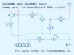
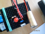
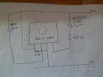
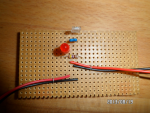
Wired one up on a small breadboard, just with an LED and resistor for indication. There are four new AA's providing 6.4v when on load, and a 100nF decoupling cap close to the S9686.

The circuit is so simple I can't see any issue there, and I've checked it repeatedly, even built again with new components on a new breadboard.

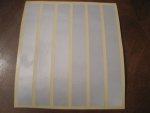
There are three types of reflector I'm trialling, the 'grey' sheet stuff, some 'hexagon' sheet, and an industrial reflector, which is the best, but very expensive !.
The problem is I'm getting no range at all. I have to shine the laser directly onto the sensor for it to trigger, even in a pitch black room.

Now, the strange thing is I built exactly the same test rig about 3 years ago, and it worked fine. Easily detected any reflector at 5ft in daylight.

So what could be different now ?. Have the lasers or the S9686's 'aged' somehow ?.

Any suggestions welcome.

Cheers,

Buzby


SAM_3104 (600 x 450).pngSAM_3105 (600 x 450).png
 
Last edited:

erco

Senior Member
It's not sensor age, mine are all 3+ years old! Any chance you connected your sensor backwards, even briefly? It's hard to tell which side is which without careful study (with my reading glasses) and perhaps one mistake is enough to fry these, not sure. Fortunately, you have an active UK supplier at
http://www.active-robots.com/hamamatsu-proximity-detector.html

BTW, I got all my info from Philo: http://www.philohome.com/sensors/lasersensor.htm

Here's another interesting site on laser triangulation once you get up and running: http://nxt-unroller.blogspot.com/2012/10/laser-sensor-for-nxt.html
 

erco

Senior Member
Did you check your laser for pulsing? You could scope the output to the laser to verify that. Supposedly 1/16 duty cycle IIRC.

Reflective surfaces vary in range. I was getting over 10 feet (no lenses) from my best material, a white reflective sticker. Even a white wall or hand triggered at 2-3 inches.
 

Buzby

Senior Member
Hi erco,

I am certain the sensor is the correct way round. If you put one in backwards it quickly gives off magic smoke, then goes pop !. ( Can you guess how I know that ? )

If I shine a non-pulsed laser direct on the sensor it has no effect, so I'm sure the pulses are there. ( Anyway, I've tried three sensors, they can't all be faulty.(?) )

Making two separate rigs, with two lots of components, makes my think I've made a simple error twice, but I can't for the life of me see what it could be.

What voltage are you using, and do you have resistor in series with the laser ?.

I've just made another, on stripboard, exactly the same behaviour.

SAM_3106 (600 x 450).png

If I use the industrial reflector I can actually see the reflected light illuminating the sensor.

I'm pulling my hair out over this !.

Cheers,

Buzby
 

erco

Senior Member
I'm using 5V (no cap) off a DC booster circuit powered by a single Li-Ion cell, much like this one: http://www.ebay.com/itm/1PC-0-9-5V-To-5V-600mA-USB-Charger-DC-DC-Converter-Step-Up-Module-New-/200953466361

My cheapie laser is pulled out of one of these: http://www.ebay.com/itm/Dual-Function-Red-Laser-Pointer-Super-Bright-LED-Flashlight-Keyring-Black-NEW-/251264282270?pt=US_Laser_Pointers&hash=item3a8084ae9e#ht_427wt_921

Per Philo, leave the SM 68 ohm resistor on the laser pointer intact. Mine had one. I wonder if you bypassed that, maybe you drew too much current and blew the S6986's pulser circuit?
 

erco

Senior Member
You can also use an LED instead of a laser for short-range tests, as God & Hamamatsu intended. :)

I can take a photo of my setup for you later today if you like.
 

Buzby

Senior Member
Hi erco,

The pulse output is a constant current, somewhere between 15 and 60mA, typically 35mA, so I don't think it could be a blown driver.

The lasers themselves I bought off eBay 3 years ago, and I can't remember the spec, they are similar to these : http://www.ebay.co.uk/itm/1-piece-650nm-red-5mW-Laser-diode-Module-DOT-3VDC-pointer-/251321570742?pt=LH_DefaultDomain_0&hash=item3a83eed5b6

I did try replacing the laser with a red LED, and could detect white paper at 4cm, so my suspicion is the laser.
Maybe the one I used 3 years ago wasn't one of these I'm trying now. Maybe it was the wrong colour red !.

Now searching deep dark crevices for a different laser ....

Cheers,

Buzby
 

Buzby

Senior Member
Hi erco,

Well, it's definitely something to do with the lasers.

I put a red LED in series with the laser, don't really know why. Now the laser can detect the reflector at 10 ft !!!.

Take the LED out, no detect. Put the LED back in, 10 ft again.

I've no idea why this works, but I'll investigate.

Cheers,

Buzby
 

erco

Senior Member
Good to hear. You did say you were using 4xAAs, about 6.4V worth. Those little laser diodes are typically driven with 4.5V from three button cells, which surely drops in use. Maybe your laser was off-spec (off frequency?) at the higher voltage but the LED dropped ~1.7V overhead and got the laser back in spec at 4.7V. Just a thought.

I was also about to suggest that maybe your indicator LED was drawing too much current and causing other problems. IIRC, I used a 1000 ohm resistor and a low current LED in my setup.
 

Buzby

Senior Member
Hi erco,

I've got 20 supposedly identical laser modules.
They are 6mm brass cylinders with two wires epoxied through a hole at the back end.

Measuring the current they pull, I found 15 were using 7mA, and 5 were using 15mA.

Doing a bit of brute force engineering I got one opened up.
It has a board with what looks like two transistors and some passives.
This is probably a constant current circuit.

My suspicion is that the volt drop of the CC circuit, plus the drop in the Hamamatus chip, is too much when running on a 5v supply.

Looking on eBay there seem to be two basic types of lasers, 3v and 5v.
The 5v ones are brass cylinders like mine.
The 3v ones have a PCB sticking out of the back, with what looks like a single resistor.
This single resistor arrangement is what is in the 'Laser Pointer' device that you hacked, and in the one I probably tested this setup with 3 years ago.

I've ordered a few 3v lasers off eBay, just waiting for China post to deliver.

Will post results then.

Cheers,

Buzby
 

John West

Senior Member
The "3V" LASER's I've used were indeed just a LASER diode with a current limiting resistor, intended for use with 3 button cells. The "5V" LASER's I've played with were higher quality (brass case, etc,) and have invariably had a simple transistor-based current limiting circuit to keep from blowing out the LASER diode when used in circuits running at a full 5V for extended periods. The 3V type were clearly designed for cheap LASER pointers. The 5V type were likely intended for commercial equipment.

I had some problems pulsing the transistor current-limited type at high pulse rates. In fact, I could barely see any output at all. The circuit in the ones I tried just wasn't meant to have a pulsed power source, certainly not at 75 kHz anyway, and couldn't keep up with the turn on, turn off rate. The cheaper resistor-limited version pulsed just fine at 75 kHz, so I used them for generating the carrier frequency of my my Hi-Fi audio transmitter.

I didn't try either type at higher or lower pulse frequencies, but assume the 5V version would work properly at some lower pulse frequency, and the 3V "resistor" version would work at both lower and higher pulse frequencies.

One of the more common LASER diode failure modes is where they still glow dimly as an LED, but can no longer be driven into the much brighter LASER excitation. When that happens, it's time to pull that one out and toss it, unless you have a use for a not very bright nor very reliable LED somewhere.

Also, as you drop the applied current you will likely see the LASER diode drop out of LASER excitation into simple dim LED operation before it stops glowing altogether, as this is indeed a second mode of operation of many fully functional LASER diodes.
 
Last edited:

Buzby

Senior Member
... I had some problems pulsing the transistor current-limited type at high pulse rates. In fact, I could barely see any output at all. ...
I think I was seeing something similar. I put my crap-o-scope on, and instead of a nice deep square-edged pulse I saw a shallow V shape, as if there was some capacitance at work.

... One of the more common LASER diode failure modes is where they still glow dimly as an LED, but can no longer be driven into the much brighter LASER excitation. ...
I'd never thought about that !. So if the laser won't lase, it will just glow ?. My tests were done in a fairly dim room, so even a non-lasing laser may have looked bright enough. A review today in daylight shows that some are definitely dim.

I await my cheap lasers and will try again !.

Thanks John for sharing your experiences. There's a lot more to these lasers than I thought.

Cheers,

Buzby
 

John West

Senior Member
Just wait till you start reading up on photon current vs electron current in the diode die, Buzby. There's a whole lot to know about semiconductor LASER diodes. More than I'll ever know, for sure, and I enjoy playing with them.

The (former) LASER glowing as if it were a weak LED (even though you are feeding it a level of current that should drive it into LASER excitation) is just one of the possible failure modes for LASER diodes, however I've seen it all too often.

The LASER's with brass sleeves are hopefully higher quality than the plastic 'Dollar Store' ones I bought, even if they only use a single resistor for current limiting. The brass is useful as a heatsink for the diode, and is likely indicative of better optics as well. Some of my plastic-shelled units had horribly distorted 'spots,' And were barely worth the dollar I spent on them.
 
Last edited:

Buzby

Senior Member
Has China post delivered yet?....
No, still waiting ......

The setup on the NXT site seems a bit over the top for what I need.
Three years ago I got 2 metres range with just the sensor, a laser, a reflector, and no lenses.
I just want to replicate what I did then.

Results will be posted when the bits arrive.

Cheers,

Buzby
 

erco

Senior Member
That NXT site mentions a cloth reflective tape which I have not tried. I have tested several different types of shiny sticker tapes, and the best I've found (yielding longest range) is called "Reflexite DOT C2" in either red or silver/white. I found an Ebay seller called doublewow who sells it and lots of other reflective stuff. You can see some of his stuff on Ebay at http://myworld.ebay.com/doublewow/

Or email him directly and tell him what you're after: zebraone@hughes.net Bill lives in Oklahoma and is a great guy, a retired FAA electronics tech. Tell him ercost sent you and you're building robot laser sensors !

BTW he also sells my second favorite reflective film, 3M Diamond grade white. His 3" x 8" sheets sell for about $2 each.

I've done some legwork, but feel free to track this stuff down on your own, of course. Any retroreflective material should work to some degree, but these particular tapes gave maximum range & reliability with this sensor in my tests.

My friend found this 2" x 10' roll (6" red/6" white-silver, repeating): http://www.ebay.com/itm/171074626640?ru=http://www.ebay.com/sch/ i.html%3F_from%3DR40%26_sacat%3D0%26_nkw%3D1710746 26640%26_rdc%3D1 The description states it's Reflexite DOT C2, but I have not tested it.

Also, I received my four lasers from Ebay yesterday. After I tear one down, I'll report my findings.
 

SteveT

Senior Member
I've got 2 different types on order, I'll see what they are like when they arrive.

The most retroreflective tape I ever saw was sewn on to our fire tunics and leggings when I used to be a fireman. From what I remember it was 3M stuff and extreemly expensive in small quantities, something in the order of £14 per foot length of 2" wide. That was quite some time ago mind. I'll post my findings when mine arrives.
 

Buzby

Senior Member
I've got three types of reflectors.

A few plastic 4" square or round industrial units, about 6mm thick, with moulded 3D cubes or pyramids under a clear face. These are fantastically reflective, and very pricey.

A short piece of stick-on tape, 100mm x 50mm, again with 3D facets, but only the thickness of stickytape. Seems to reflect just as good as the industrial unit.

A 500mm x 600mm sheet of grey stick-on, made by Avery ( but no part number, Grrr !!! ). Not as reflective as the other two, but good enough for what I need.

The industrial reflectors I collected during my years of working on conveyor control systems. I've no idea where the short tape came from.
I bought the big sheet a few years ago, it cost about £7.50, I just need to remember where I bought it from !. ( It wasn't eBay. )

When my new lasers arrive I'll try them all again.

One thing I want to try is the effect of rotation of the 'grey' sheet around the axis of the beam. Some datasheets ( e.g. https://www.mysick.com/eCat.aspx?go=Accessories&Cat=Row&At=Fa&Cult=English&ProductID=7142&Category=Produktfinder ) seem to indicate that the axial orientation of the target seriously affects the reflectance. I don't know if this is true of all 'grey sheet' type reflectors, but it would be good to know if it is.

Now I just need some lasers !.

Cheers,

Buzby
 

SteveT

Senior Member
Hi Guys,

just a brief update on <my> progress as my tape has arrived and I've had a quick play to determine distances etc.

first of all this is the circuit I'm using....

image001.png

I decided to use the high side switch after measuring the current at pin 3 on the Hamamatsu IC as 59mA. Don't want to try and turn that on with a Picaxe pin.
@Erco, yes I saw your comment about the mark/space ratio but didn't want to take any chances.

I'm using these laser diodes ..... http://www.ebay.co.uk/itm/2-x-5mW-650nm-Red-5V-Laser-Dot-Diode-Module-Head-2PCS-/290919705146?pt=UK_Sound_Vision_Amplifier_Parts&hash=item43bc2a6a3a

which are supposedly 5mW.

The tape I ordered was.... tape1.jpg
http://www.ebay.co.uk/itm/Silver-High-Quality-High-Intensity-Reflective-Tape-Vinyl-Roll-Cheap-Reliable-/221189658518?pt=LH_DefaultDomain_3&var=&hash=item791a713139
and... (2 picture limit - next post)
http://www.ebay.co.uk/itm/SIX-STICKY-WHITE-REFLECTIVE-STRIPS-VINYL-TAPE-8-x-1-/281087784749?pt=UK_Motorcycle_Parts&hash=item417223372d

The first one is tottaly rubbish for our purposes - as soon as the laser 'dot' hits any part of the
pattern it just splits up into multiple very weak reflections, so much so that the best distance I
could get a reflected activation was in the order of about 4 inches.

The second tape is much better in that it reflects back a single dot. Much better distances,
multiple feet but didn't bother to check exactly. If that's what we want we might as well use a small
mirror.

What Buzby and I want is what erco has used but if possible from this side of the pond. A tape that acts like the
first tape but with the brightness of the second.

Further tape research needed or ordering from erco's side of the pond. BTW could not get any joy from your links, either of you.
 

SteveT

Senior Member
2nd post for 1 picture..... tape2.jpg

BTW the above (post #22) was without a lens.

I've found that a reasonable lens and not toooooo big is all 3 elements of a 3 lens pocket loupe.
 
Last edited:

AllyCat

Senior Member
Hi Steve,

I'm not convinced that Q2 is doing anything useful in your diagram. IMHO the circuit would behave in almost exactly the same way with the "VBE multiplier" divider chain (R3 + R4) connected directly to the base of Q3.

The second tape is much better in that it reflects back a single dot. Much better distances,
multiple feet but didn't bother to check exactly. If that's what we want we might as well use a small
mirror.
Thanks for those interesting ebay links, but surely a "reflector" (in this context) returns light to the same direction from which it was received whilst a mirror generally transmits it in a different direction. Certainly there's no (theoretical) difference if the light happens to strike at exactly right-angles to its surface, but the advantage of a "reflector" is that it doesn't need to be accurately aligned to the direction of the light beam.

Cheers, Alan.
 

SteveT

Senior Member
Hi Steve,

I'm not convinced that Q2 is doing anything useful in your diagram. IMHO the circuit would behave in almost exactly the same way with the "VBE multiplier" divider chain (R3 + R4) connected directly to the base of Q3.
No idea (I'll try it though). I just lifted it from the NXT site. I always thought that to switch the positive rail you had to use a high side switch. I don't know a great deal about transistor circuits. My intention was to use the Picaxe to switch Q2 via R3 which in turn would switch Q3 and power the laser diode??

Thanks for those interesting ebay links, but surely a "reflector" (in this context) returns light to the same direction from which it was received whilst a mirror generally transmits it in a different direction. Certainly there's no (theoretical) difference if the light happens to strike at exactly right-angles to its surface, but the advantage of a "reflector" is that it doesn't need to be accurately aligned to the direction of the light beam.

Cheers, Alan.
Fair enough, point taken. I'll set up a more rigid test rig and do some more tests with the tape I've already got.
 

SteveT

Senior Member
I don't know why the link has stopped working, so here is a copy of one of the datasheets that the link should point to.

View attachment 14843

As you will see, it talks about orientation of the sheet and how this affects reflectance.
Am I correct in thinking they are talking about 20 degrees either side of 12, 3, 6 and 9 o'clock for the position of the receiver from the laser diode. Obviously the closer together the greater the detection area (near to far) - depth of field in photographic terms??
 

Dippy

Moderator
Have you managed to get the range you want yet? I've only skimmed this thread so may have missed something significant.

I used an Optek OPV302 onto a reflector and got ranges of metres with a 30mA pulse. I was really surprised how small yours is.
Is your receiver 'way out' in the beam wavelength parameter?
For my app, to get the best results, I had to use a Photo-D with no built-in IR filter and get some filter from a third-party.
(it was years ago so can't remember details).

I don't know whether it applies to your Ebay modules but there are special reflectors for narrow beam laser intended to give a sharper return signal.
They're sometimes called 'microprism' and have much smaller reflective elements.
Not cheap.
 

Buzby

Senior Member
... I've only skimmed this thread so may have missed something significant. ...
I got two significant results from this thread,

(1) Laser modules with built-in current limiting don't work at high pulse rates.

(2) Lasers can stop lasing, but still shine a quite bright beam.

For the range I need, and the range erco got, the 'grey' sheet stuff works OK.
This is made from tiny glass spheres, but whether the stuff I've got is specifically for lasers I don't know.

And I'm still waiting for my lasers ......
 

John West

Senior Member
What I got from this thread was, don't order LASER's from Buzby's supplier. :)

P.S. As both Premelec and I live in Boulder, Colorado, we may not be receiving anything shipped to us for awhile, anyway.
 

Dippy

Moderator
Haha yes. I don't know Buzby's supplier but at least he's found it educational and got the result he wanted.

I must admit I tend to use suppliers that also supply a full technical data sheet - it can save a lot of money and time.
I don't mean that to sound smug, but if you get the component(s) that the design says has a 99% chance of working then you can usually get the project running in short time.
 

John West

Senior Member
Yep. Documentation is a real plus. I'm often willing to buy something that's broken if it includes tech documentation. I bought a nice old Heathkit amateur radio transceiver a while back that included the complete original assembly manual, parts list, schematics, theory of operation and troubleshooting guide. The seller very emphatically assured me that it worked, but I took one look at the manual and said I didn't really care if it worked or not. With those docs, anyone who can solder could easily fix it.

When it comes to LASER's, I've seen very good docs occasionally with the mid-priced ones, and no docs at all much more often with the cheap ones ($1 US.) When I play with those, I tend to buy a handful of them and "characterize" them by letting the magic smoke out of a couple of them. Also, I got a LASER power meter from PICAXer Ray Burnette, so I have all the critical info but wavelength. I suppose I can dig up a decent diffraction grating if I need to know that info, but so far I haven't had the need.

Good specs save a lot of hassle and measurement, and sometimes whole projects.

Of course, with some of the LASER specs, I don't even know what they mean. Photonics, (optics) is a different world from electronics.
 

Buzby

Senior Member
... but if you get the component(s) that the design says has a 99% chance of working then you can usually get the project running in short time.
The sensor has a complete and comprehensive datasheet, but it specifies using an LED, not a laser, so it's uncharted territory.

When I bought the lasers, 3 years ago, I was a bit naive. I thought lasers were all much the same, and if they shone red they were working, but now I know better.

The supplier of my recent order marked the lasers as despatched on 29 Aug, the day after I ordered them, so I should have them real soon now !.
 

Dippy

Moderator
Good data sheets for receivers should specifiy the peak wavelength (and a distribution graph) for sensitivity. As well as response times etc.

The , for example, IR Laser data sheets should also define peak wavelength of output.

If you superimpose the graphs (whether graphically or arithmetically) it'll give you a first stab at optical sensitivity.
The Optek OPV300/302 lasers I used had a peak wavelength of 850nm with rise-fall times of 100 picoSeconds, the former offering data rates of 2.5Gbps - so enough data were there before purchase.

Often they will give (or allow you to calculate) the maximum frequency of operation. e.g an actual MHz/GHz value or, for a rough idea, the peak pulse current @1uS pulse width.

Without these types of figures you are into experiment-and-hope. In fairness, often successfully - but nevertheless it is a gamble.
Anyway, I hope your data sheets gave you enough info to allow you to choose - or was it all based on price? ;)
 

Buzby

Senior Member
Price was a major factor, I needed 24 of these circuits, but I did do a bit of datasheet work before I started.

Unfortunately I can't really use the information from the S6986 datasheet. ( Datasheet in post #2 )

The graph shows that the sensor's peak sensitivity is at 800nm, and drops to about 95% at 850nm.
The characteristics table shows the sensitivity at 940nm as being 2uW/mm2.
I have no idea what uW/mm2 the sensor is receiving after the retroreflector has done it's job, and I don't have any tools to measure it.
A good guess, based on data for similar reflectors, might be that the retroreflector returns 60% of the laser beam, but what power is the beam to start with ?.

Without tools to measure uW/mm2, and details about the power of the laser, I saw 'suck it and see' as being the only way to progress !.
 

SteveT

Senior Member
Also, I got a LASER power meter from PICAXer Ray Burnette, so I have all the critical info but wavelength. I suppose I can dig up a decent diffraction grating if I need to know that info,
I asked the Queen about wavelength but she can't of heard me because she didn't reply. If she had replied I'm sure she would have answered "it depends on the length of the journey" :rolleyes:
 

Buzby

Senior Member
My lasers arrived today !.

Ordered on 28th August.
Supplier posted on 29th August, ( or at least printed the label on that day. )
Arrived on 26th October.

Now I just need to remember where I've put my detectors !
 

Buzby

Senior Member
I found my detectors !.

Range with either the industrial reflector or the prismatic tape is easily 7.5m ( 26ft ), but no more than 2m with the 'grey' reflector.
 
Top