PWM as input
- Thread starter Hansen
- Start date
westaust55
Moderator
More information would certainly be helpful.Is it possible to use Picaxe
to work with PWM on the input from 800 pwm to 2000 PWM
Plan is to work with the signal come from RC reviver
800 to 2000 PWM ? Or is that Hz (frequency)?
COUNT and PULSIN are tentative options.
See PICAXE manual 2 (or the "BASIC Commands" like/button at top of forum pages for informating including max signal frequencies at various PICAXE clock speeds.
yes it servo output from the RC receiver that the 1st 4 channel us to control a ( flight or boart or heli)
I don't want to control them, I want to split each channel op in 5 level
1 level shut be 1st 20%
2 level shut be 2nd 20%
3 level shut be 3nd 20% same as centre and normal for 3 off the channel
4 level shut be 4th 20%
5 level shut be 5th 20%
product will be 4 var. ( b1 to b4 ) where have a value from 1 to 5
it the first 1/2 program
2nd part use the value in B1-4 to control Light
westaust55
Moderator
As srnet states, more clear description would be very helpful.
You know what you want to achieve - try to prevent assumptions/guesses and the solution can come much afster.
Working in the assumptions raised thus far,
If the pulse durations are between 800 us and 2000 us, then, using the PULSIN command and assuming a PICAXE clock frequency of 4 MHz then the min value returned is 80 and the max is 200. Subtract 80 and you have a value in the range 0 to 120.
Since you want 5 “bands”/stages then use the modulus function where
<returned value> // 24
will give a value of 0 to 4 with returned values of 0 to 119, but 5 if a 2000 us pulse is received. Alternatively divide by 25 ( // 25 )
I want to read 4 channelIts not at all clear to me, and I guess most of us, what you are trying to do.
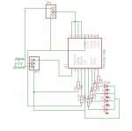
Do you have a circuit diagram ?
How many RC channels are you reading, how many outputs do you want to control ?
All necessary information before readers start guessing or making assumptions.
the lower value on a input will be around 1100 PWM nad the higest around 1900 PWMAs srnet states, more clear description would be very helpful.
You know what you want to achieve - try to prevent assumptions/guesses and the solution can come much afster.
Working in the assumptions raised thus far,
If the pulse durations are between 800 us and 2000 us, then, using the PULSIN command and assuming a PICAXE clock frequency of 4 MHz then the min value returned is 80 and the max is 200. Subtract 80 and you have a value in the range 0 to 120.
Since you want 5 “bands”/stages then use the modulus function where
<returned value> // 24
will give a value of 0 to 4 with returned values of 0 to 119, but 5 if a 2000 us pulse is received. Alternatively divide by 25 ( // 25 )
possible it have to be change so it read the neutral position on all 4 input in the start-up ( power on sequence)
main function is to turn the 6 light channel if any channel change from normally start-up position
sub function make some kind off light show, that illustrate the movement off the stick(input)
each arm will have different colour light strip
Jeremy Harris
Senior Member
The confusion seems to stem from the misused terminology.
RC command signals use PPM, Pulse Position Modulation, not PWM which is Pulse Width Modulation.
To read RC PPM you just need to decode the position of the pulse you are interested in relative to the longer start pulse in the frame. This article has an illustration: http://www.hobbytronics.co.uk/decode-rc-control-ppm
the PPM signal is the 1 that use From transmitter to the receiverThe confusion seems to stem from the misused terminology.
RC command signals use PPM, Pulse Position Modulation, not PWM which is Pulse Width Modulation.
To read RC PPM you just need to decode the position of the pulse you are interested in relative to the longer start pulse in the frame. This article has an illustration: http://www.hobbytronics.co.uk/decode-rc-control-ppm
I Want the Servo output from the RC receiver
on my Spectrum i have 7 channel for servo and the 1st 4 channel i want to USE
2 external link
http://www.e-radiocontrol.com.ar/en/?Documentation:Decoder:PWM
https://sites.google.com/site/2007arduino/hardware-description/rc-interface-dxi-dxo
Reading the output from an RC receiver can be done very simply using the pulsin command. This will result in a value of about 100 to 200 representing the position of the transmitter stick for that channel. You will need to but the pulsing command in an infinite loop, and take whatever action you want base on the value read. You could get clever with some code at the start of the program in order to find the maximum, neutral and minimum pulse widths, or use some trial-and-error testing to find these values, and hence set thresholds for various actions. Below is some code that I wrote for a 4-channel RC switch which you may find useful as a basis for your own code.
Code:
'Radio control 4 channel switch using PICAXE-18
'Kevin Goom  8 October 2005
'Use, abuse, modify distribute freely, but at your own risk.
'Any channel can operate in latched or unlatched operation.
'For latched operation tie legs 18,17,16,15 to +5V for channel A to D respectively.
'Outputs (legs 6,7) will then go high the first time the receiver pulse goes above the threshold, and low the next.
'Outputs (legs 8,9) will then go high the first time the receiver pulse goes below the threshold, and low the next.
'For unlatched operation,legs 6,7 are high when the receiver pulse goes above the threshold and vice-versa.
'For unlatched operation,legs 8,9 are high when the receiver pulse goes below the threshold and vice-versa.
'Change the values b11 as desired to change the switching points.
'PICAXE-18 connections are:
' Leg 1   (In2)           Pulse input from radio receiver
' Leg 2   (Serial Out)
' Leg 3   (Serial in) Tie to Ground through 10K resistor
' Leg 4   (Reset)  Tie to +5V through 4.7K resistor
' Leg 5      Ground
' Leg 6   (Out0)  Channel A output
' Leg 7   (Out1)  Channel B output
' Leg 8   (Out2)  Channel C output
' Leg 9   (Out3)  Channel D output
' Leg 10  (Out4)  Not connected
' Leg 11  (Out5)  Not connected
' Leg 12  (Out6)  Not connected
' Leg 13  (Out7)  Not connected
' Leg 14     +5V
' Leg 15  (In6)  Channel D latching option (+5V=latching, ground=non-latching)
' Leg 16  (In7)  Channel C latching option
' Leg 17  (In0)  Channel B latching option
' Leg 18  (In1)  Channel A latching option
symbol OutA=0      'Name channel A output pin (leg6)
symbol OutB=1      'Name channel B output pin (leg7)
symbol OutC=2      'Name channel C output pin (leg8)
symbol OutD=3      'Name channel D output pin (leg9)
symbol LatchedA=pin1     'Name channel A latch option pin (leg18)
symbol LatchedB=pin0     'Name channel B latch option pin (leg17)
symbol LatchedC=pin7     'Name channel C latch option pin (leg16)
symbol LatchedD=pin6     'Name channel D latch option pin (leg15)
symbol Pulse_Width=w6     'Name measured input pulse width
symbol Prev_Pulse_Width=b2    'Name previous measured input pulse width
symbol Pulse_In=2      'Name pulse input pin (leg1)
'Initialise
Restart:
   pins=%00000000      'Set all outputs low initially and on loss of input
Start:
   pulsin Pulse_In,1,Pulse_Width   'Measure and store input pulse
   if Pulse_Width<50 or Pulse_Width>250 then Restart 'Go back if input pulse lost
   b10= LatchedA
   b11=180      'Set channel A threshold to 1.80 ms
   b6=0      'Set to switch channel A (Out0)
   b7=1      'Set to switch channel A (and B) to up mode
   gosub Check     'Check for up-switching on channel A
   b10= LatchedB
   b11=160      'Set channel B threshold to 1.60 ms
   b6=1      'Set to switch channel B (Out1)
   gosub Check     'Check for down-switching on channel B
   b10= LatchedC
   b11=140      'Set channel C threshold to 1.40 ms
   b6=2      'Set to switch channel C (Out7)
   b7=0      'Set to switch channel C (and D) to down mode
   gosub Check     'Check for down-switching on channel C
   b10= LatchedD
   b11=120      'Set channel D threshold to 1.20 ms
   b6=3      'Set to switch channel B (Out1)
   gosub Check     'Check for down-switching on channel B
   Prev_Pulse_Width=Pulse_Width  'Reset previous pulse width to current pulse width
goto Start      'Go back to measure input pulse again

Check:
   if b10=1 then Latch                     'Check whether channel is latched operation
       'Unlatched operation
   if Pulse_Width>b11 and b7=1 then Out_On   'Check whether pulse is longer than threshold, up mode
   if Pulse_Width<b11 and b7=0 then Out_On   'Check whether pulse is longer than threshold, down mode
   low b6              'Turn off output if pulse beyond threshold
   Return         'Exit Check subroutine
Out_On:
   high b6         'Turn on output if pulse beyond threshold
   Return              'Exit Check subroutine
Latch:      'Latched Operation
   if Prev_Pulse_Width<b11 and b7=1 then Thold    'Check whether previous pulse beyond threshold, up mode
   if Prev_Pulse_Width>b11 and b7=0 then Thold    'Check whether previous pulse beyond threshold, down mode
   Return         'Exit Check subroutine if previous pulse above threshold
Thold:         'Previous pulse below threshold
   If Pulse_Width<b11 and b7=1 then Finish   'Check whether pulse is beyond threshold, up mode
   If Pulse_Width>b11 and b7=0 then Finish   'Check whether pulse is beyond threshold, down mode
   toggle b6        'Toggle output if pulse is beyond than threshold
Finish:
Returnwestaust55
Moderator
Good "pick-up" Jeremy.The confusion seems to stem from the misused terminology.
RC command signals use PPM, Pulse Position Modulation, not PWM which is Pulse Width Modulation.
To read RC PPM you just need to decode the position of the pulse you are interested in relative to the longer start pulse in the frame. This article has an illustration: http://www.hobbytronics.co.uk/decode-rc-control-ppm
From the subsequent OP's response
[quotwe]the PPM signal is the 1 that use From transmitter to the receiver [/quote]
that would seem to to be the right call.
But the earlier description at post 5 for 5 stages suggested picking a 100% in steps of 20% from a PWM for a ramped up activation of LEDs, rather than up to 7 channels from one RC signal where individual bits can be set on or off from the 1 RC channel..
So we need Hansen to confirm more clearly exactly what the aim is.
Hansen, please provide a plain English description (step by step) and a sketch with timing charts rather than a block diagram showing no real functionality is needed.
afacuarius
New Member
Reading the output from an RC receiver can be done very simply using the pulsin command. This will result in a value of about 100 to 200 representing the position of the transmitter stick for that channel. You will need to but the pulsing command in an infinite loop, and take whatever action you want base on the value read. You could get clever with some code at the start of the program in order to find the maximum, neutral and minimum pulse widths, or use some trial-and-error testing to find these values, and hence set thresholds for various actions. Below is some code that I wrote for a 4-channel RC switch which you may find useful as a basis for your own code.Code:'Radio control 4 channel switch using PICAXE-18 'Kevin Goom 8 October 2005 'Use, abuse, modify distribute freely, but at your own risk. 'Any channel can operate in latched or unlatched operation. 'For latched operation tie legs 18,17,16,15 to +5V for channel A to D respectively. 'Outputs (legs 6,7) will then go high the first time the receiver pulse goes above the threshold, and low the next. 'Outputs (legs 8,9) will then go high the first time the receiver pulse goes below the threshold, and low the next. 'For unlatched operation,legs 6,7 are high when the receiver pulse goes above the threshold and vice-versa. 'For unlatched operation,legs 8,9 are high when the receiver pulse goes below the threshold and vice-versa. 'Change the values b11 as desired to change the switching points. 'PICAXE-18 connections are: ' Leg 1 (In2) Pulse input from radio receiver ' Leg 2 (Serial Out) ' Leg 3 (Serial in) Tie to Ground through 10K resistor ' Leg 4 (Reset) Tie to +5V through 4.7K resistor ' Leg 5 Ground ' Leg 6 (Out0) Channel A output ' Leg 7 (Out1) Channel B output ' Leg 8 (Out2) Channel C output ' Leg 9 (Out3) Channel D output ' Leg 10 (Out4) Not connected ' Leg 11 (Out5) Not connected ' Leg 12 (Out6) Not connected ' Leg 13 (Out7) Not connected ' Leg 14 +5V ' Leg 15 (In6) Channel D latching option (+5V=latching, ground=non-latching) ' Leg 16 (In7) Channel C latching option ' Leg 17 (In0) Channel B latching option ' Leg 18 (In1) Channel A latching option symbol OutA=0 'Name channel A output pin (leg6) symbol OutB=1 'Name channel B output pin (leg7) symbol OutC=2 'Name channel C output pin (leg8) symbol OutD=3 'Name channel D output pin (leg9) symbol LatchedA=pin1 'Name channel A latch option pin (leg18) symbol LatchedB=pin0 'Name channel B latch option pin (leg17) symbol LatchedC=pin7 'Name channel C latch option pin (leg16) symbol LatchedD=pin6 'Name channel D latch option pin (leg15) symbol Pulse_Width=w6 'Name measured input pulse width symbol Prev_Pulse_Width=b2 'Name previous measured input pulse width symbol Pulse_In=2 'Name pulse input pin (leg1) 'Initialise Restart: pins=%00000000 'Set all outputs low initially and on loss of input Start: pulsin Pulse_In,1,Pulse_Width 'Measure and store input pulse if Pulse_Width<50 or Pulse_Width>250 then Restart 'Go back if input pulse lost b10= LatchedA b11=180 'Set channel A threshold to 1.80 ms b6=0 'Set to switch channel A (Out0) b7=1 'Set to switch channel A (and B) to up mode gosub Check 'Check for up-switching on channel A b10= LatchedB b11=160 'Set channel B threshold to 1.60 ms b6=1 'Set to switch channel B (Out1) gosub Check 'Check for down-switching on channel B b10= LatchedC b11=140 'Set channel C threshold to 1.40 ms b6=2 'Set to switch channel C (Out7) b7=0 'Set to switch channel C (and D) to down mode gosub Check 'Check for down-switching on channel C b10= LatchedD b11=120 'Set channel D threshold to 1.20 ms b6=3 'Set to switch channel B (Out1) gosub Check 'Check for down-switching on channel B Prev_Pulse_Width=Pulse_Width 'Reset previous pulse width to current pulse width goto Start 'Go back to measure input pulse again Check: if b10=1 then Latch 'Check whether channel is latched operation 'Unlatched operation if Pulse_Width>b11 and b7=1 then Out_On 'Check whether pulse is longer than threshold, up mode if Pulse_Width<b11 and b7=0 then Out_On 'Check whether pulse is longer than threshold, down mode low b6 'Turn off output if pulse beyond threshold Return 'Exit Check subroutine Out_On: high b6 'Turn on output if pulse beyond threshold Return 'Exit Check subroutine Latch: 'Latched Operation if Prev_Pulse_Width<b11 and b7=1 then Thold 'Check whether previous pulse beyond threshold, up mode if Prev_Pulse_Width>b11 and b7=0 then Thold 'Check whether previous pulse beyond threshold, down mode Return 'Exit Check subroutine if previous pulse above threshold Thold: 'Previous pulse below threshold If Pulse_Width<b11 and b7=1 then Finish 'Check whether pulse is beyond threshold, up mode If Pulse_Width>b11 and b7=0 then Finish 'Check whether pulse is beyond threshold, down mode toggle b6 'Toggle output if pulse is beyond than threshold Finish: Return
Hello
Try goom make this project, but I can not work, not if you connect something wrong, because they assemble as it appears in the code.
not turn any LED, I used a futaba rc remote control, with the design of 2 channels I had no problem, but finding this of 4 channels, I have not gotten it to work.
can you help me ??
thanks
Hola
Intento realizar este proyecto de goom, pero no logro que funcione, no se si conecte algo mal, ya que lo arme tal y como aparece en el codigo.
no prende ningun led, he utilizado un control remoto rc futaba, con el diseño de 2 channels no tuve ningun problema, pero al encontrar este de 4 channels, no he conseguido que funcione.
Podrian ayudarme ??
Gracias
afacuarius
New Member
When reading the code goom, I found that the receiver signal enters Leg 1 (In2) that would be for the channel b (left, right)
but for the channel c and d??? (up and down)
or the same channel is used to generate the 4?
Regards
Al leer el codigo de goom, encontre que la señal del receptor entra a Leg 1(In2) eso seria para el canal a y b (izquierda, derecha)
pero para el canal c y d ??? (arriba y abajo)
o se utiliza el mismo canal para generar los 4 ?
Saludos