Program works in simulator and not in the chip?
- Thread starter GAP
- Start date
premelec
Senior Member
Please give more specific information - often times it's hardware wiring not being correct. Specify chip - does anything work? Post Copy part of program not working and good picture of your hardware so we can see wiring... so many possibilities... so little information you've given... ")
That post was made in desparation.Perception is reality Boriz.
@GAP please give us a copy of your program, ensuring that we are fully aware of the chip that is the target. A photo of the chip layout of your circuit and maybe a circuit diagram would all help, maybe immensely.
Your ball!
The chip is a 14M2, I loaded the program and it worked once as per the simulator indications.
The next time I ran it (after a power down/up) it did not work at all , no changes were made.
A second chip was programmed to eliminate the posibility of a faulty chip.
It is a simple program that reads the adc input ans starts a pair of LEDs flashing alternatety.
Then I run it is the simulator the LED indicators flash at a satisfactory rate but when I run it via the chip the LEDs just flash at a high speed.
There is an issue also with the triggers but it is the flash rate that is my biggest problem.
Below is a copy of the program please ignore the refernces to Boom up and down that has an issue which is a seperate problem.
All I want is the lights working reliably at this point in time.
On another note is there anywhere, other than the manuals, that I can get some tuition in the basic language, as trying to understand it is the biggest stumbling block that I am encountering in learning to program at this point.
I am in Aust so any type of tuition would be real helpful.
Code:
;This program reads the adc input from C.4(left) or C.0 (right) to trigger flashing
;lights and to lower or raise a boom on a model train layout.
;The program will trigger on whichever adc input changes from high to low first,
;when this happens it starts the flashing lights and lowers the boom.
;It then waits till the opposite adc input to the triggering input changes
;from high to low, signifying that the train has passed
;and then turns off the lights and raises the boom.


symbol left=b0
symbol right=b1
SYMBOL countr = b2
SYMBOL servopin = b.4
SYMBOL servopina = b.5

start:

	Low B.1				;Set B.1 as an output and low
	Low B.2				;Set B.2 as an output and low
	b5 = 0                    	;this is to keep track of the state of the lights

	readadc c.4,left       		;read adc into variable b0
	readadc c.0,right     		;read adc into variable b1

	readadc c.4,left        	;looks at both inputs
	readadc c.0,right

	if left>150 then         	;if left is greater than 150 then flash lights and lower booms

		GoSub ChangeLights
		GOSub BoomDown
		GoSub ChangeLights

		do
			readadc c.0,right
    			If b4 =5 Then
       			 GoSub ChangeLights
       			 b4 = 0
    		end if
  		inc b4
	loop while right<150

		do
			readadc c.0,right
			if b4 =5 Then
        			 GoSub ChangeLights
        			 b4 = 0
    		end if
    		inc b4
	loop while right>150
	end if

	if right>150 then
	do
			readadc c.4,left
			if b4 =5 Then
				GoSub ChangeLights
        			b4 = 0
        	end if
        	inc b4
        loop while left<150

		do
			readadc c.4,left
			if b4 =5 Then
        			 GoSub ChangeLights
        			 b4 = 0
    		end if
    		inc b4
	  loop while left>150

	GoSub ChangeLights
	GoSub BoomUp

	else
	GoTo start

end if

GoTo Start


ChangeLights: ;this sets which light is on/off based on the value of the b5 variable
		 ;and then XORs (flips it between 1 and 0) it so that next time the sub is called
		 ;it switches them back.


			if b5 = 0 then
	    		low B.1
	       	high B.2
	    		pause 300
	    		low B.2
	    		High B.1

			else

    			high B.1
    			low B.2
	    		pause 300
	    		high B.2
	    		low B.1

			endif

	b5 = b5 XOR 1

	Return


BoomUp:
    servo B.4,150			;set servos at 150
    servo B.5,150

    for countr = 140 to 225
    	servo B.4,countr
        servo B.5,countr

    servo B.5, countr
    if b4=5 Then
        GoSub ChangeLights
        b4=0
    end if
    pause 1
    next countr				;increment counter by one count
Return


BoomDown:
    servo b.4,225   ;set servos at 225
    servo b.5,225

    for countr = 225 to 140 step -1
        servo b.4,countr
        servo b.5,countr

    servo B.5,countr
    if b4=5 Then
        GoSub ChangeLights
        b4=0
    end if
    pause 1
    next countr				;decrement by one count
ReturnJimPerry
Senior Member
Probably is the simulator delay - to make it simpler to find the correct delay make a symbol delaylight = w6 then w6=1000 (say) and replace all the pause 300 statements with pause delaylight.
Then you only have to change 1 line to vary the flash delay
EDIT: MartinM57 pointed out I had used b6 - only valid to 255 changed to w6 for 65K
Then you only have to change 1 line to vary the flash delay
EDIT: MartinM57 pointed out I had used b6 - only valid to 255 changed to w6 for 65K
Last edited:
inglewoodpete
Senior Member
Welcome to the real world where 0's and 1's are not necesserily what you think they are.
Unless you've done something really silly, the PICAXEs are unlikely to be damaged. They're tough little beasties.
You don't describe your hardware at all. Do you have the download curcuit (10k + 22k resistors) permanently connected to your PICAXE?
Initially, leave your programming cable connected to your circuit while you debug your hardware and software.
Add the following directives near the top of the Symbols.
Add this command in the line before the Start: label
Add the following command immediately after the ReadADC commands (you don't need to repeat the ReadADC commands like you have in the code you posted).
Report back what gets reported to the terminal window and we'll see how else we can help.
Unless you've done something really silly, the PICAXEs are unlikely to be damaged. They're tough little beasties.
You don't describe your hardware at all. Do you have the download curcuit (10k + 22k resistors) permanently connected to your PICAXE?
Initially, leave your programming cable connected to your circuit while you debug your hardware and software.
Add the following directives near the top of the Symbols.
Code:
#PICAXE 14M2
#Terminal 4800
Code:
SerTxd("Booted 14M2", CR, LF)
Code:
SerTxd("Left=", #left, ", Right=", #right, CR, LF)Not looked at the detail, but b6=1000 will fail (well it won't fail, but it won't do what you expect)....the Bx variables can only hold values 0 to 255 inclusiveProbably is the simulator delay - to make it simpler to find the correct delay make a symbol delaylight = b6 then b6=1000 (say) and replace all the pause 300 statements with pause delaylight.
Then you only have to change 1 line to vary the flash delay
Welcome to the real world where 0's and 1's are not necesserily what you think they are.
Unless you've done something really silly, the PICAXEs are unlikely to be damaged. They're tough little beasties.
You don't describe your hardware at all. Do you have the download curcuit (10k + 22k resistors) permanently connected to your PICAXE?
Initially, leave your programming cable connected to your circuit while you debug your hardware and software.
Add the following directives near the top of the Symbols.
Add this command in the line before the Start: labelCode:#PICAXE 14M2 #Terminal 4800
Add the following command immediately after the ReadADC commands (you don't need to repeat the ReadADC commands like you have in the code you posted).Code:SerTxd("Booted 14M2", CR, LF)
Report back what gets reported to the terminal window and we'll see how else we can help.Code:SerTxd("Left=", #left, ", Right=", #right, CR, LF)
1. The hardware consists of a breadboard with a 14 pin chip holder for the picaxe.
2. There are 2 lots of LDRs connected as voltage dividers between +5V and 0V with the centre connected ot C.4 and C.0 (adc)
When one LDR is covered the inputs see a change at the centre (about 128 for half voltage), one LDR is seeing the ambient light and the other is being covered. When installed on the railway one will be outside the track and one between the rails.
3. Connected to pins B.1 B.2 there are LEDswith the other side connected to V.
4. connected to B.5 via a resistor is a servo signal lead, the servo is powered off the 5V rail.
There is no download circuit on the bread board, I have an 08M2 and a 14M2 download circuits on seperate small boards mounted on a piece of wood.
I download the program into the chip then remove the chip and put it in the holder on the breadboard to run the program.
I have had no experience with debug at all and have only been shown how to use the simulator.
My knowledge of programming is limited to following the examples in the manuals but when it come to putting them together I am just guessing and sometimes I get lucky.
Not a good method I know but that is how it is, for example I copied one of the "if then do loop" commands and changed left to right and got syntax errors but the one I copied did not have an error.
The above example is one of my sources of frustration hence the plea for some tuition.
I am radio tradesman but lived in the analogue world the whole of my working years, so only a passing knowledge of digital.
westaust55
Moderator
You do not need a variable at all. Define a constant with:Whoops should have said a w6 word variable
SYMBOL delaylight = 1000
Then save a variable entirely and use it as:
PAUSE delaylight
westaust55
Moderator
@GAP,
Suggest that you read up on the TOGGLE command.
Then one command can replace the need to store the current state of the LEDs, and separate groups of high and low commands to flash them.
Looks like another model railway boom gate lriject.
If you do a search of the PICAXE forum ther was another quite recent thread on the same topic.
@ West aust55 the other thread was me I walked away from this for a while but have come back to it.@GAP,
Suggest that you read up on the TOGGLE command.
Then one command can replace the need to store the current state of the LEDs, and separate groups of high and low commands to flash them.
Looks like another model railway boom gate lriject.
If you do a search of the PICAXE forum ther was another quite recent thread on the same topic.
If I remember there is some code that you recommended in there.
I'll give toggle a go.
Input buffer
I have added the code as instructed and after programming a window opened with this fast scrolling list in the "input buffer" (see copy below).
I haven't the slightest clue of what I am looking at, which is par for the course.
Welcome to the real world where 0's and 1's are not necesserily what you think they are.
Unless you've done something really silly, the PICAXEs are unlikely to be damaged. They're tough little beasties.
You don't describe your hardware at all. Do you have the download curcuit (10k + 22k resistors) permanently connected to your PICAXE?
Initially, leave your programming cable connected to your circuit while you debug your hardware and software.
Add the following directives near the top of the Symbols.
Add this command in the line before the Start: labelCode:#PICAXE 14M2 #Terminal 4800
Code:SerTxd("Booted 14M2", CR, LF)
Add the following command immediately after the ReadADC commands (you don't need to repeat the ReadADC commands like you have in the code you posted).
Report back what gets reported to the terminal window and we'll see how else we can help.Code:SerTxd("Left=", #left, ", Right=", #right, CR, LF)
I have added the code as instructed and after programming a window opened with this fast scrolling list in the "input buffer" (see copy below).
I haven't the slightest clue of what I am looking at, which is par for the course.
Code:
Left=11, Right=11
Left=10, Right=10
Left=10, Right=9
Left=11, Right=15
Left=12, Right=13
Left=11, Right=12
Left=10, Right=11
Left=10, Right=9
Left=11, Right=15
Left=12, Right=14
Left=11, Right=13
Left=11, Right=11
Left=10, Right=10
Left=10, Right=9
Left=11, Right=14
Left=11, Right=13
Left=11, Right=12
Left=10, Right=11
Left=10, Right=9
Left=11, Right=15
Left=12, Right=14
Left=11, Right=12
Left=11, Right=11
Left=10, Right=10
Left=10, Right=9
Left=11, Right=14
Left=11, Right=13
Left=11, Right=12
Left=10, Right=10
Left=10, Right=9
Left=11, Right=15
Left=12, Right=13
Left=11, Right=12
Left=10, Right=11
Left=10, Right=9
Left=11, Right=15
Left=11, Right=14
Left=11, Right=12
Left=11, Right=11
Left=10, Right=10
Left=10, Right=9
Left=11, Right=14
Left=11, Right=13
Left=11, Right=12
Left=10, Right=10
Left=10, Right=9
Left=11, Right=15
Left=12, Right=14
Left=11, Right=12
Left=10, Right=11
Left=10, Right=9
Left=11, Right=15
Left=12, Right=14
Left=11, Right=12
Left=10, Right=11
Left=10, Right=10
Left=10, Right=9
Left=11, Right=14
Left=11, Right=13
Left=11, Right=12
Left=10, Right=10
Left=10, Right=9
Left=11, Right=15
Left=12, Right=13
Left=11, Right=12
Left=10, Right=11
Left=10, Right=9
Left=11, Right=15
Left=12, Right=14
Left=11, Right=12
Left=10, Right=11
Left=10, Right=10
Left=10, Right=9
Left=11, Right=14
Left=11, Right=13
Left=11, Right=11
Left=10, Right=10
Left=10, Right=9
Left=11, Right=15
Left=11, Right=13
Left=11, Right=12
Left=10, Right=11
Left=10, Right=9
Left=11, Right=15
Left=12, Right=14
Left=11, Right=12
Left=10, Right=11
Left=10, Right=10
Left=10, Right=9
Left=11, Right=14
Left=11, Right=13
Left=11, Right=11
Left=10, Right=10
Left=10, Right=9
Left=11, Right=15
Left=11, Right=13
Left=11, Right=12
Left=10, Right=10
Left=10, Right=9
Left=11, Right=15
Left=11, Right=14
Left=11, Right=12
Left=10, Right=11
Left=10, Right=10
Left=10, Right=8
Left=11, Right=14
Left=11, Right=12
Left=10, Right=11
Left=10, Right=10
Left=10, Right=9
Left=11, Right=14
Left=11, Right=13
Left=11, Right=12
Left=10, Right=10
Left=10, Right=9
Left=11, Right=15
Left=11, Right=13
Left=11, Right=12
Left=10, Right=10
Left=10, Right=9
Left=11, Right=15
Left=12, Right=14
Left=11, Right=12
Left=10, Right=11
Left=10, Right=10
Left=10, Right=9
Left=11, Right=14
Left=11, Right=13
Left=11, Right=11
Left=10, Right=10
Left=10, Right=9
Left=11, Right=14
Left=11, Right=13
Left=11, Right=12
Left=10, Right=10
Left=10, Right=9
Left=11, Right=15
Left=11, Right=13
Left=11, Right=12
Left=10, Right=11
Left=10, Right=9
Left=11, Right=15
Left=12, Right=14
Left=11, Right=12
Left=10, Right=11
Left=10, Right=10
Left=10, Right=9
Left=11, Right=14
Left=11, Right=13
Left=11, Right=11
Left=10, Right=10
Left=10, Right=9
Left=11, Right=14
Left=11, Right=13
Left=11, Right=12
Left=10, Right=10
Left=10, Right=9
Left=11, Right=15
Left=12, Right=14
Left=11, Right=12
Left=10, Right=11
Left=10, Right=9
Left=11, Right=15
Left=12, Right=14
Left=11, Right=12
Left=10, Right=11
Left=10, Right=10
Left=10, Right=9
Left=11, Right=14
Left=11, Right=13
Left=11, Right=11
Left=10, Right=10
Left=10, Right=9
Left=11, Right=15
Left=12, Right=13
Left=11, Right=12
Left=10, Right=11
Left=10, Right=9
Left=11, Right=15
Left=12, Right=14
Left=11, Right=12
Left=10, Right=11
Left=10, Right=9
Left=11, Right=15
Left=12, Right=14
Left=11, Right=13
Left=11, Right=11
Left=10, Right=10
Left=10, Right=9
Left=11, Right=14
Left=11, Right=13
Left=11, Right=12
Left=10, Right=10
Left=10, Right=9
Left=11, Right=15
Left=12, Right=14
Left=11, Right=12
Left=10, Right=11
Left=10, Right=9
Left=11, Right=15
Left=12, Right=14
Left=11, Right=12
Left=10, Right=11
Left=10, Right=10
Left=10, Right=9
Left=11, Right=14
Left=11, Right=13
Left=11, Right=11
Left=10, Right=10
Left=10, Right=9
Left=11, Right=14
Left=11, Right=13
Left=11, Right=11
Left=10, Right=10
Left=10, Right=9
Left=11, Right=14
Left=11, Right=13
Left=11, Right=12
Left=10, Right=10
Left=10, Right=9
Left=11, Right=15
Left=11, Right=14
Left=11, Right=12
Left=10, Right=11
Left=10, Right=9
Left=11, Right=15
Left=12, Right=14
Left=11, Right=13
Left=11, Right=11
Left=10, Right=10
Left=10, Right=9
Left=11, Right=14
Left=11, Right=13
Left=11, Right=11
Left=10, Right=10
Left=10, Right=9
Left=11, Right=15
Left=11, Right=13
Left=11, Right=12
Left=10, Right=10
Left=10, Right=9
Left=11, Right=15
Left=12, Right=14
Left=11, Right=12
Left=10, Right=11
Left=10, Right=10
Left=10, Right=9
Left=11, Right=14
Left=11, Right=13
Left=11, Right=11
Left=10, Right=10
Left=10, Right=9
Left=11, Right=15
Left=11, Right=13
Left=11, Right=12
Left=10, Right=10
Left=10, Right=9
Left=11, Right=15
Left=12, Right=14
Left=11, Right=12
Left=10, Right=11
Left=10, Right=9
Left=11, Right=15
Left=11, Right=14
Left=11, Right=13
Left=11, Right=11
Left=10, Right=10
Left=9, Right=8
Left=13, Right=21
Left=17, Right=24
Left=20, Right=23
Left=17, Right=21
Left=16, Right=20
Left=16, Right=19
Left=15, Right=14
Left=11, Right=12
Left=10, Right=10
Left=10, Right=9
Left=11, Right=15
Left=12, Right=13
Left=11, Right=12
Left=10, Right=10
Left=10, Right=9
Left=11, Right=15
Left=12, Right=14
Left=11, Right=12
Left=10, Right=11
Left=10, Right=9
Left=11, Right=15
Left=12, Right=14
Left=11, Right=12
Left=10, Right=11
Left=10, Right=10
Left=9, Right=8
Left=13, Right=21
Left=17, Right=23
Left=17, Right=22
Left=16, Right=21
Left=16, Right=19
Left=15, Right=15
Left=12, Right=13
Left=11, Right=11
Left=10, Right=10
Left=10, Right=9
Left=11, Right=14
Left=11, Right=13
Left=11, Right=11
Left=10, Right=10
Left=10, Right=9
Left=11, Right=14
Left=11, Right=13
Left=11, Right=12
Left=10, Right=10
Left=10, Right=9
Left=11, Right=14
Left=11, Right=13
Left=11, Right=11
Left=10, Right=10
Left=10, Right=9
Left=11, Right=14
Left=11, Right=13
Left=11, Right=12
Left=10, Right=10
Left=10, Right=9
Left=11, Right=15
Left=11, Right=13
Left=11, Right=12
Left=10, Right=10
Left=10, Right=9
Left=11, Right=15
Left=11, Right=13
Left=11, Right=12
Left=10, Right=10
Left=10, Right=9
Left=11, Right=15
Left=11, Right=13
Left=11, Right=12
Left=10, Right=10
Left=10, Right=9
Left=11, Right=15
Left=12, Right=13
Left=11, Right=12
Left=10, Right=10
Left=10, Right=9
Left=11, Right=15
Left=12, Right=14
Left=11, Right=12
Left=10, Right=10
Left=10, Right=9
Left=11, Right=15
Left=11, Right=13
Left=11, Right=12
Left=10, Right=10
Left=10, Right=9
Left=11, Right=15
Left=11, Right=13
Left=11, Right=12
Left=10, Right=10
Left=10, Right=9
Left=11, Right=15
Left=11, Right=13
Left=11, Right=12
Left=10, Right=10
Last edited by a moderator:
inglewoodpete
Senior Member
This is where you'll have to help yourself. The PICAXE does not appear to be rebooting all the time, so that is a good sign.
The left input looks very stable but the right one is changing in a regular sawtooth fashion. Is that supposed to happen? Check that the right sensor is connected properly.
You now need to apply the left and right values to your code. What should it do and compare that to what actually happens. Add more "SerTxd" commands as I have suggested, to other parts of your code to see what happens.
I am now totally confused because that readout was from the picaxe in my programming setup. ie nothing is commented just the 10K and the 22K programming resistors.This is where you'll have to help yourself. The PICAXE does not appear to be rebooting all the time, so that is a good sign.
The left input looks very stable but the right one is changing in a regular sawtooth fashion. Is that supposed to happen? Check that the right sensor is connected properly.
You now need to apply the left and right values to your code. What should it do and compare that to what actually happens. Add more "SerTxd" commands as I have suggested, to other parts of your code to see what happens.
From post #10
Do you have the 22K / 10K download resistors on your breadboard?
If not do you have the serial in pin ( c.5 ) pulled down with a resistor?
A circuit diagram would be helpful - even a neat freehand sketch
This may be significant.There is no download circuit on the bread board, I have an 08M2 and a 14M2 download circuits on seperate small boards mounted on a piece of wood.
I download the program into the chip then remove the chip and put it in the holder on the breadboard to run the program.
Do you have the 22K / 10K download resistors on your breadboard?
If not do you have the serial in pin ( c.5 ) pulled down with a resistor?
A circuit diagram would be helpful - even a neat freehand sketch
inglewoodpete
Senior Member
Firstly, I didn't see your post #10 when I replied last. Sorry I missed it. It sort of explains why one of the ADC readings is cycling up and down: it's probably 50Hz mains radiation being picked up by the unterminated ADC input.
Not having a download circuit on your (not) working circuit makes it almost impossible to debug both code and hardware. I suggest you add a stereo socket with flying leads soldered to your project so that you can see debugging data. The 10K and the 22K programming resistors are required, of course, but they are required regardless: the PICAXE will not be stable without them.
Once you can log the output from the PICAXE when it is plugged into your project, post some of it so we can see what is happening. Actually, you should be able to see the ADC values in the log change as you illuminate/shade the LDRs. When posting long pieces or code or logs, wrap
Code:
tags around it to keep it compact.It might be a good idea to consider this
http://www.techsupplies.co.uk/epages/Store.sf/en_GB/?ObjectPath=/Shops/Store.TechSupplies/Products/AXE029
You can then leave your Picaxe chip on the breadboard for programming and testing.
However, you will still need a resistor 27K ~ 33K from you serial in pin to earth if your final circuit does not include the standard download resistors.
Firstly, I didn't see your post #10 when I replied last. Sorry I missed it. It sort of explains why one of the ADC readings is cycling up and down: it's probably 50Hz mains radiation being picked up by the unterminated ADC input.
Not having a download circuit on your (not) working circuit makes it almost impossible to debug both code and hardware. I suggest you add a stereo socket with flying leads soldered to your project so that you can see debugging data. The 10K and the 22K programming resistors are required, of course, but they are required regardless: the PICAXE will not be stable without them.
Once you can log the output from the PICAXE when it is plugged into your project, post some of it so we can see what is happening. Actually, you should be able to see the ADC values in the log change as you illuminate/shade the LDRs. When posting long pieces or code or logs, wrapCode:tags around it to keep it compact.[/QUOTE] OK I was thinking along the same lines about the download circuit, after reading the manuals again. I have a schematic of the circuit but don't know how to put it on here. I have tried using the program with the servo physically disconnected (as it shares the same power supply as the chip I do have another power supply but it does not share a common ground as recommended in the manuals) and any mention of the servo in the program "rem'd" out.
Just connect the two grounds ( -ve ) together. ONLY the -ve lines.but it does not share a common ground as recommended in the manuals)
I think we need to go right back to the beginning. We need a circuit diagram - go advanced when you submit a reply and have a look at manage attachments at the bottom of the page.
Then post the current program and we can be sure we are all talking about the same thing.
inglewoodpete
Senior Member
I concur. The drawing can be hand drawn if that's all you can manage. It must be complete, though. Then scan or photograph the drawing and post it as a JPG file.I think we need to go right back to the beginning. We need a circuit diagram - go advanced when you submit a reply and have a look at manage attachments at the bottom of the page.
Then post the current program and we can be sure we are all talking about the same thing.
westaust55
Moderator
If all else fails, it is not hard to draw a simple schematic in MS Paint (comes with all versions of Windows) or even Excel. I often use Excel as a mechanisim when away from home to create a part circuit for helping others.
At home, I typically use DIPTRACE, free for hobby use with a limitation of about 500 component holes which is ample for most projects to draw my schematics.
At home, I typically use DIPTRACE, free for hobby use with a limitation of about 500 component holes which is ample for most projects to draw my schematics.
How did you choose the ADC values for deciding if the LDR is covered or not? You'll need the debug numbers to get an idea of what the actual value will return, sometimes it isn't exactly what was expected. Once you have those, which are the numbers the sertxd line you are reading in the debug window while the controller is running, you only need to modify your program for it to work properly.
For the fluctuations in readings, try adding both a 22uF capacitor across the power supply + and GND, as well as a 0.1uF/100nF farad across +v and GND as close to the IC as possible to reduce induced noise from motors, fluorescent lighting, etc. The (extremely simplified) reason for 2 capacitors is the 22uF will be an Electrolytic type, which have rather high Equivalent Series Resistance and lower "response time", so they are better at stabilizing the power for lower frequency fluctuations, while the 0.1uF mono caps are very low ESR and "fast" reacting, which keeps the noise in the power from being fed to the controller, as well as "holding up" the supply voltage when the controller is changing states.
These are called "bypass capacitors" or "decoupling capacitors", as they "bypass" any AC component, such as noise, to ground, as capacitors pass AC and block DC. There are many articles written on the topic, though I believe the 0.1uF capacitor at the IC power pins should be added to the "minimum components" of a Picaxe circuit. Whenever random glitches are found on a circuit without bypass capacitors, adding them will often fix the glitches.
Here is a helpful link for bypass capacitors with animations
inglewoodpete
Senior Member
Hi Brass, welcome to the PICAXE forum. You may have jumped into the middle of this unfolding story. At this point, we don't know what the 'real' ADC readings look like in the actual circuit because the the ADC inputs were open circuit when the data was logged. Stay tuned!
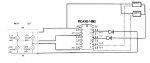
View attachment Crossing 14M2 schematic.doc
This is the schematic of my breadboard setup it is a word document. Hopefully I have added it right.
I have substitued my power supply with a battery pack and that lights still flash rapidly.
I found an old copy of the program (with the XOR line suggested by West Aust55 included) which had a note that this worked OK but now it doesn't.
As I have limited time to really play with this due to work etc it might be a long term project.
@ Brass the ADC level was decided on by measuring the LDR values under the same light source that is now being used to test the circuit.
They are in a voltage divider arrangment, I also am familiar with coupling and decoupling caps and have considered them to remove any interference from the servo but as it is not in circuit at the moment I have disregardee any influence from the servo.
inglewoodpete
Senior Member
Yes, I can see your circuit diagram. The first thing I noticed is that you have not drawn in the resistor/s between pin C.5 (Serial in for programming) and 0v. As a couple of people including myself have mentioned previously: it won't run without this pin tied low.This is the schematic of my breadboard setup it is a word document. Hopefully I have added it right.
To simplify things for readers,
I've extracted the diagram and re-posted as a jpg.
e
I've extracted the diagram and re-posted as a jpg.
e
Attachments
-
 26 KB Views: 15
hippy
Ex-Staff (retired)
I think an important question is ( on your real hardware with everything connected ); does everything else work as required and as expected, is it only that the lights flash too fast which is the problem ?I have substitued my power supply with a battery pack and that lights still flash rapidly.
GAP
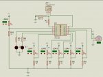
I've been working on this for a while. See my code and schematic (schematic from PICAXE VSM and works with lights flashing at balanced speed when servos are moving and when they're not.
LDRs 1 to 5 are placed between rails. LDR6 is the 'control' LDR placed outside rails to detect normal level of light, whether it's full bright daylight or darker for evening operation. This gives the control ADC level, which varies according to light intensity across the layout. I then subtract 6 from it (this value can be varied in the code) so the gates won't lower until the light on any of the other LDRs is lower.
Pin C.3 goes to ground (not shown) and the PICAXE has a 100 nF decoupling capacitor between +VE and ground.
delayTillLower is time between lights starting to flash and gates starting to lower.
delayTillRaise is time between train clearing LDRs and gates raising.
timeToFlashStop is time between gates fully raised and lights stopping flashing.
flasherspeedstatic is the slower flashing rate of the LEDs.
flasherspeedmoving is the faster flashing rate of the LEDs.
The reason for the 2 rates, albeit that they are very close, was in my breadboard experiment circuit the flashing rate changed when different parts of the program were being run (more or less going on) so that has been factored into it.
Any questions, please ask. If this is of no use to you then please ignore.
Angie
Code:
#picaxe 14M2

start0:
	suspend 1
declare:
'	dirsC = %000110
'	dirsB = %000011

;	PINS
	symbol LED1 = C.1
	symbol LED2 = C.2
	symbol LDRControl = C.4
	symbol servoPin = B.1
'	symbol bell = C.3
	symbol LDR1 = C.0
	symbol LDR2 = B.5
	symbol LDR3 = B.4
	symbol LDR4 = B.3
	symbol LDR5 = B.2

;	VARIABLES
	symbol servoPosition = bit1	  ; 1 = raised, 0 = lowered
	symbol gatesPosition = bit2	  ; 1 = raised, 0 = lowered
	symbol LL1 = b7			  ; variable to store sensed light level
	symbol LL2 = b8			  ; variable to store sensed light level
	symbol LL3 = b9			  ; variable to store sensed light level
	symbol LL4 = b10			  ; variable to store sensed light level
	symbol LL5 = b11			  ; variable to store sensed light level
	symbol baseLDRLevel = b12	  ; store non-interrupted light level for comparison
	symbol servoMax = b13		  ; maximum raised movement for gates
	symbol servoMin = b14		  ; maximum lowered movement for gates
	symbol flasherspeed = w1  	  ; LED Flashing speed
;	b26 -					    for loops
;	b27 - 				    for loops

;	FIXED
	symbol timeToFlashStop = 2000		; delay before flashing stops after gates raised
	symbol flasherspeedstatic = 340	; set speed of lights flashing when gates static
	symbol flasherspeedmoving = 345	; set speed of lights flashing when gates moving
	flasherspeed = flasherspeedstatic

	symbol delayTillRaise = 2000		; delay till the gates start to raise after track clear
	symbol delayTillLower = 1000		; delay after flashing starts till the gates start to lower
	symbol servospeed = 60			; set speed of servo

	servoMax = 200
	servoMin = 120
	servoPosition = 1
	gatesPosition = 1

	servo servoPin, servoMax 		; initialise servo to raised state
	low LED1					; initialise flasher leds to off
	low LED2

; 	BOOM CONTROL
	do

		READADC LDRControl, baseLDRLevel
		READADC LDR1, LL1
		READADC LDR2, LL2
		READADC LDR3, LL3
		READADC LDR4, LL4
		READADC LDR5, LL5

		baseLDRLevel = baseLDRLevel - 8

		if gatesPosition = servoPosition then

			if LL1 < baseLDRLevel or LL2 < baseLDRLevel or _
				LL3 < baseLDRLevel or LL4 < baseLDRLevel or _
				LL5 < baseLDRLevel and gatesPosition = 1 then

				gatesPosition = 0 ; gates lowered
				gosub lowerGates
sertxd ("here 2", 13, 10)

			elseif LL1 >= baseLDRLevel and LL2 >= baseLDRLevel and _
				LL3 >= baseLDRLevel and LL4 >= baseLDRLevel and _
				LL5 >= baseLDRLevel and gatesPosition = 0 then

				gatesPosition = 1 ; gates raised
				gosub raiseGates
sertxd ("here 3", 13, 10)

			endif

		endif

;		sertxd ("Active Point, ", #baseLDRLevel, " - ")
;		sertxd ("ADC, ", #LL1, ", ", #LL2, ", ", #LL3, ", ", #LL4, ", ", #LL5, 13, 10)

	loop


lowerGates:
;	sertxd ("Lowering Gates",13,10)
	flasherspeed = flasherspeedstatic
	restart 1
	pause delayTillRaise
	flasherspeed = flasherspeedmoving
	for b27 = servoMax to servoMin step -1
		servopos servoPin, b27
		pause servospeed
	next b27
	servoPosition = 0


	return

raiseGates:
;	sertxd ("Raising Gates",13,10)
	flasherspeed = flasherspeedstatic
	pause delayTillLower
	flasherspeed = flasherspeedmoving
	for b27 = servoMin to servoMax
		servopos servoPin, b27
		pause servospeed
	next b27
	servoPosition = 1
	pause timeToFlashStop
	suspend 1
	low LED1
	low LED2
'	low bell

	return

start1:	; LIGHT CONTROL
'	toggle bell
	toggle LED2
	pause flasherspeed
	do
		toggle LED1
		toggle LED2
		pause flasherspeed
	loop
Attachments
-
 121.9 KB Views: 11
Code:
start:

	Low B.1				;Set B.1 as an output and low
	Low B.2				;Set B.2 as an output and low
	b5 = 0                    	;this is to keep track of the state of the lights

	readadc c.4,left       		;read adc into variable b0
	readadc c.0,right     		;read adc into variable b1


	readadc c.4,left        	;looks at both inputs
	readadc c.0,right

	if left>150 then         	;if left is greater than 150 then flash lights and lower booms

		GoSub ChangeLights
		'GOSub BoomDown
		GoSub ChangeLights

		do
			readadc c.0,right
    			If b4 =5 Then
       			 GoSub ChangeLights
       			 b4 = 0
    		end if
  		inc b4
	loop while right<150

		do
			readadc c.0,right
			if b4 =5 Then
        			 GoSub ChangeLights
        			 b4 = 0
    		end if
    		inc b4
	loop while right>150
	end if

	if right>150 then
	do
			readadc c.4,left
			if b4 =5 Then
				GoSub ChangeLights
        			b4 = 0
        	end if
        	inc b4
        loop while left<150

		do
			readadc c.4,left
			if b4 =5 Then
        			 GoSub ChangeLights
        			 b4 = 0
    		end if
    		inc b4
	  loop while left>150

	GoSub ChangeLights
	'GoSub BoomUp

	else
	GoTo start

end if

GoTo Start


ChangeLights: ;this sets which light is on/off based on the value of the b5 variable
		 ;and then XORs (flips it between 1 and 0) it so that next time the sub is called
		 ;it switches them back.


			if b5 = 0 then
	    		low B.1
	       	high B.2
	    		pause 1000
	    		low B.2
	    		High B.1

			else

    			high B.1
    			low B.2
	    		pause 1000
	    		high B.2
	    		low B.1

			endif

	b5 = b5 XOR 1

	Return


'BoomUp:
    'servo B.4,150			;set servos at 150
    'servo B.5,150

    'for countr = 140 to 225
    'servo B.4,countr
    'servo B.5,countr

    'servo B.5, countr
    'if b4=5 Then
       ' GoSub ChangeLights
       ' b4=0
   ' end if
    'pause 1
    'next countr				;increment counter by one count
'Return


'BoomDown:
    'servo b.4,225   ;set servos at 225
    'servo b.5,225

    'for countr = 225 to 140 step -1
        'servo b.4,countr
        'servo b.5,countr

    'servo B.5,countr
    'if b4=5 Then
        'GoSub ChangeLights
        'b4=0
    'end if
    'pause 1
    'next countr				;decrement by one count
'ReturnI found that I had changed the pause between high and low on the lights from 1000mS to 300mS because of the time delay in the simulator, lesson learned document all changes.
I now have to figure out how to get the servo part to do its thing correctly because at the moment it is a bit erratic ie goes up and down at random and halts the lights for long periods of time.
In the previous thread "tech support" suggested using parallel processing and I was given a program the does that but it doesn't work, (author used 08M2 to test functions in isolation and not on an14M2) so i am going to use that as a training aid.
Has anybody used or has an opinion on "Logicator" because I can understand flow charts way better than looking at code.
I have tied C.5 low as well as suggested.
Again thanks for the help, standby for the next cry for help.
Opinion: Majoring in Logicator flow charts rather than Baisc code will effectively paint you into a corner and reduce the number of members of this forum can effectively give you meaningful support.
Good to be able to read and produce a flow chart, but the implementation is unable to fully exploit the full command set of the PICAXE Basic language.
A picture may be worth a thousand words, but I suggest that your efforts would be better spent learning to read code. Create a few small programs with Logicator, translate to Basic and study the correspondence between the two. It will come fairly quickly and practice makes perfect.
Basic is also free to use and likely to allow you to write longer and more complicated programs than you would be able to achieve using Logicator.
I may be well out of line, but I would consider Logicator to be a very good trainer, but not a real programming tool. Not that GUI programming aids are necessarily bad, but they take a lot more work on the part of the designers to produce a good end result. Invariably it becomes a compromise and offers reduced facility over the standard Basic code option of using the PICAXE Program Editor suite.
erco
Senior Member
Although I have not tried Logicator, I tend to agree with Paix on this one. BASIC is not difficult to learn, significantly easier than C, which is what Arduino essentially uses. Learning BASIC will likely offer you increased flexibility in your program, as well as lay the foundations for learning other languages. Plenty of eager help is available in the forum, and many excellent examples are online.
My using Logicator as a training aid is exactly what I am doing, but with the level of programming I am aspiring to it probably would suffice..Opinion: Majoring in Logicator flow charts rather than Baisc code will effectively paint you into a corner and reduce the number of members of this forum can effectively give you meaningful support.
Good to be able to read and produce a flow chart, but the implementation is unable to fully exploit the full command set of the PICAXE Basic language.
A picture may be worth a thousand words, but I suggest that your efforts would be better spent learning to read code. Create a few small programs with Logicator, translate to Basic and study the correspondence between the two. It will come fairly quickly and practice makes perfect.
Basic is also free to use and likely to allow you to write longer and more complicated programs than you would be able to achieve using Logicator.
I may be well out of line, but I would consider Logicator to be a very good trainer, but not a real programming tool. Not that GUI programming aids are necessarily bad, but they take a lot more work on the part of the designers to produce a good end result. Invariably it becomes a compromise and offers reduced facility over the standard Basic code option of using the PICAXE Program Editor suite.
I stare at code trying to make sense of it and it may as well be written in chinese.
I can think logically but when using basic I just have so much trouble getting for example "if this happens then do this" into a usable format all I seem to get is syntax errors and the manuals I find are just not newbie friendly.
Maybe it is just my age and lack of time to experiment kicking in.