My first PICAXE project - Chicken lights / Greenhouse watering

PaulRB

Senior Member
Updated - Chicken house lights Mk II

Hi all,

A word of encouragement for anyone working themselves up to starting their first project. I found the whole PICAXE thing really easy. Hopefully you will too.

I do have the advantage of being a programmer for part of my career, but haven't done any electronics since Uni, many many years ago.

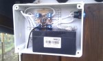
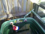
The first project I set myself was to build a circuit to automatically control lights in a Chicken house. I'm hoping the same design will work just as well for watering the greenhouse.

The lights will come on at dusk and stay on for a couple of hours. What constitutes "dusk" and "a couple of hours" can be set by the user - the circuit has a "learn" mode for this. For greenhouse watering, it will only be a couple of minutes rather than hours, with the lights replaced by a cheap boat bilge pump submerged in a water butt.

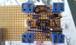
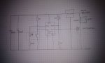
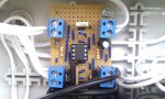
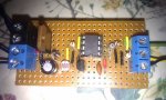
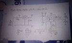
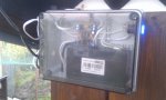
A PICAXE 08M2 is used, and LDR senses the light level and a logic-level FET controls the lights. The whole thing runs on a 12V battery, kept topped up by a solar cell.

The lights can be switched on or off at any time be pressing an illuminated button. Pressing the button for 5 seconds puts the circuit in "learn" mode where it records the light level at that point and times how long the user leaves the light on. It then repeats this daily.
IMAG0371.jpgIMAG0372.jpg
Code:
;	Dusk activated light/pump timer

;	P.Beard 14/8/2011
#picaxe 08m2

symbol	timerload = 1		; lights/pump etc output pin
symbol	lightlevel  = 2 		; light level analog input pin
symbol	pushbutton = pin3	; Pushbutton input pin
symbol	pushbuttonLED = 4	; LED (inside pushbutton) output pin

symbol	interruptmask = %00001000	; interrupt on Pin3 (pushbutton)
symbol	interruptvalue = %00001000	; when Pin 3 high
symbol	daymode = 0
symbol	duskmode = 1
symbol	nightmode = 2
symbol	learnmode = 4
symbol	shortbuttonclick = 1
symbol	longbuttonpress = 20
symbol	currentmode = b0		; learn/run mode 
symbol	dusk = b2 				; light level at dusk
symbol	day = b3 				; min light level during day
symbol	ontime = w3				;  time load has been on so far
symbol	onlength = w4			; required load on-time
symbol	dusksaved = 0				; addresses in non-volatile memory
symbol	onlengthsaved = 1

data		dusksaved, (64)
data		onlengthsaved, (20, 0)		; approx a minute

main:

	setfreq k31						; clock setting for lowest power consumption
	currentmode = daymode
	low timerload
	low pushbuttonLED
	read dusksaved, dusk				;  read saved dusk level from non-volatile memory
	day = dusk + 50					;  prevent a small change in light level causing switch to day mode
	read onlengthsaved, word onlength 	; read on length from non-volatile memory

	do

		select currentmode
		case daymode
			readadc lightlevel, b1
			if b1 <= dusk then
				currentmode = duskmode
				high timerload
				ontime = 0
			end if
		case duskmode
			inc ontime
			if ontime > onlength then
				currentmode = nightmode
				low timerload
			end if
		case nightmode
			readadc lightlevel, b1
			if b1 >= day then
				currentmode = daymode
			end if
		case learnmode
			inc ontime
		end select

		toggle pushbuttonLED	; flash the led to show timer working
		toggle pushbuttonLED
		setint interruptmask, interruptvalue
		pause 20	; approx 3 seconds at 31KHz clock
		setint off
	loop

interrupt:

	b1 = 1
	do while pushbutton = 1 	; time how long pushbutton pressed
		inc b1
	loop

	if b1 >= longbuttonpress then

		currentmode = learnmode
		high pushbuttonLED		; show user we are in learn mode
		readadc lightlevel, dusk	; capture the dusk light level
		write dusksaved, dusk	;  save dusk level to non-volatile memory
		day = dusk + 50
		high timerload
		ontime = 0
	elseif b1 >= shortbuttonclick then
		select currentmode
		case daymode, nightmode
			currentmode = duskmode
			high timerload
			ontime = 0
		case duskmode
			currentmode = nightmode
			low timerload
		case learnmode
			currentmode = nightmode
			onlength = ontime
			write onlengthsaved, word onlength	; save onlength to non-volatile memory
			low pushbuttonLED
			low timerload
		end select

	endif

	setint interruptmask, interruptvalue
	return

end
 
Last edited:

eclectic

Moderator
Welcome to the Forum Paul.

An excellent introduction. :)

Could you now provide us with information
re. the schematics?

e
 

PaulRB

Senior Member
I don't have any fancy software for drawing up schematics, it was all done on the back of an envelope!
Here's a closeup of the circuit before soldering. Spot the missing component (the LDR fell off before I took the pic without my realising - should be bottom left just to the right of the terminal block).IMAG0369.jpg
Also there are a couple of serious mistakes here which I only found after soldering and had to un-do some of it! I had a diode the wrong way round, and also got PICAXE input/outputs 3 and 4 mixed up in my head... much cursing followed).
I used the standard PICAXE-08 Proto board to build a simplified version of the circuit and to program the chip. I use AXEPAD under Ubuntu 10.04 and the USB programming cable, all of which worked perfectly first time.
 

westaust55

Moderator
Well done Paul.
As you say, you have done programming in the past and this is reflected in good indentation of the program - a few more comments might help programming newbies but certinainly not difficult to follow the program.

With respect to drawing a schematic, without trying to start a string of posts on which CAD package is best, many here use DIPTRACE.
Saved on this forum are some additional library files which can be included into DIPTRACE to provide more specific PICAXE IC's with pin designations. Also included in those library files are many other support chips frequently used with PICAXE in the same format.
See posts 2 and 3 in this thread:
http://www.picaxeforum.co.uk/showthread.php?10576
 

PaulRB

Senior Member
Thanks for the feedback!

That layout software looks great for larger projects, but overkill for my current level. I'll stick to my envelope backs for now and keep that in mind for the future. Also its $75 if you want to keep it for more than 30 days, and it only works on Windows, and I haven't got to grips with WINE yet.
 

westaust55

Moderator
DIPTRACE is available as free version without time limit but with a 300 hole limit for non-profit use only.
That suits many smaller home projects.
Noted that being Windows and MAC OS based only may be a dilemma for you however.
 

eclectic

Moderator
Tjis should work for all computer systems ;-)

1. Print out the attached diagram.

2. Draw out the schematic, using the dots as guides.

3. Scan / photograph

4. Post the jpg as an attachment to the thred.

e
 

Attachments

MPep

Senior Member
I thought "Tjis" was a program. Just re-read and noted should have been This. Having a blonde moment ;)
 

SteveT

Senior Member
DIPTRACE is available as free version without time limit but with a 300 hole limit for non-profit use only.
You can get a free serial number from them to upgrade to 500 hole limit if you only use it for hobby use.

BTW big thanks to you and Mycroft for the libraries.

Steve
 
Last edited:

PaulRB

Senior Member
So, anyway, apologies for the crude schematic, but how did I do?

It works, but could it be better with any software or component changes?

I tried to minimise the component count - did I miss any tricks?

Will the circuit cope Ok with the water pump do you think?
 

eclectic

Moderator
Two quick questions.

1. Can you supply a datasheet for the Mosfet?

2. The same for the waterpump.
(Or at least the basic details.)

e
 

PaulRB

Senior Member
Here's the fet:

Http://www.rapidonline.com/netalogue/specs/47-0552.pdf

I found the datasheet for the pump:

http://www.mackengineering.co.uk/product_downloads/RULE model 25D.pdf

I think my main concern is as much the board and its connections as the components. I tried to make big fat sausages of solder along the paths the motor current will take.

The pump data sheet says that a 2.5 amp fuse is appropriate, so the current won't exceed that for long but could it spike higher at startup?

How much current can a link made of bell wire take? Or a heavily soldered track?

I'm worried something will go pop the first time the pump is activated!
 
Last edited:

papaof2

Senior Member
There's a chart here http://www.interfacebus.com/PWB_External_Trace_Capacity.html that gives current capacity of various track widths of different thickness copper . Find the current in the upper part of the chart, come across to the 10C line on the graph and drop down to the lower part of the graph. Where the vertical line intersects the copper plating weight, you go left and read the track width needed.

A track that's 0.1 inch wide should be OK for 2.5 amps.

What gauge is the bell wire? If it's 18 gauge, then this chart http://www.powerstream.com/Wire_Size.htm indicates it's OK for 2.3 amps in power distribution (that's 24/7 service) so it should be fine for your application.

John
 

PaulRB

Senior Member
Thanks John, sounds like I should be ok then.

Even though the stripboard I'm using has 0.1" copper conductors, I notice they are far narrower around the holes! In the current bearing tracks, I have left component legs long, bent them flat along the strips and heavily soldered them down.

Just noticed I made a mistake on the hand-drawn schematic. I drew the switch pulling the input pin down to 0v instead of up to 5v. If I had done that, a couple of minor changes to the code would be needed.

The installed circuit has now been working for over a week. Yesterday I hooked up two more of the led strips in a second, larger hen house, to the same circuit. Even after 15 mins running all 3 led strips, the FET is still stone cold, which is reassuring.

Thanks everyone for the help & advice. I'll let you know how the pump/watering project goes.
 

MPep

Senior Member
Even though the stripboard I'm using has 0.1" copper conductors, I notice they are far narrower around the holes! In the current bearing tracks, I have left component legs long, bent them flat along the strips and heavily soldered them down.
Another way is to solder 5A or 10A fuse wire along the tracks. Remember to try and keep high current paths short. transients can upset the operation of an otherwise stable circuit.
Well done on your project.
 

PaulRB

Senior Member
Hi all,

8 months later, spring has arrived and the greenhouse watering project is installed and working.

Some problems at first, as the solar panel in the greenhouse had developed a fault (quickly fixed with a bit of soldering) and the battery had almost run flat. This meant when the pump came on, the voltage dropped so much that the picaxe reset. Battery now recharged and all is well. Photos attached:IMAG0504.jpgIMAG0500.jpg

...And now I realise I could have made a better decision in the design. Rather than using an LDR to detect the arrival of dusk and switching on the pump for a fixed (albeit programmable) time, what I should have done is use a soil moisture detector! So I have been searching the forum, and others on the web for advice on this.

Many home-made soil moisture detectors use a gypsum (i.e. plaster of paris) plug to embed the metal rods in (nails, bare wire etc). But my wife tells me that plaster could be slightly poisonous to the plants... So maybe just stainless steel rods? Any advice please from forum members who have solved this one?

Thanks,

Paul
 

PaulRB

Senior Member
Update: January 2013: Chicken House Lights Mk II !

Following a stoat attack in November 2012 when we lost a number of birds, we decided to boost the security of the chook's compound. As well as an extra layer of finer (.5") weldmesh applied to the existing weldmesh (2" heavy gauge), we laid down more hardcode to deter burrowing and, to "top it off", an electrified wire around the top (6') to deter any climbing predators.

The energiser for the electric wire needed a much higher capacity battery, so we purchased a 85Ahr deep-cycle "leisure" battery, around the size of a car battery. To attempt to keep this charged up, a new 20W monocrystaline panel replaced the old 4.5W poly. The new panel is mounted vertically to make the most of winter sun. A Kemo charge controller prevents overcharging.

While wiring up all this new kit, I got something wrong, and released the magic smoke from several of the components of the original lights controller. The 08m2 was undamaged, but the power FET and one of the diodes were fried. The stripboard was also damaged, so the whole thing had to go in the bin, with the exception of the picaxe.

So a great excuse to design the Mk II. Mostly the same, but with 2 major extra features:

Firstly, the lights (4 x 3W white LED strips in 3 different houses) now fade up and down over 5~10 seconds, rather than just switching instantly on or off. This not only looks cool, but may be less of a sudden surprise for the birds when the lights come on. One of our cockerels, Angel, tended to leap in the air with a loud squawk, and then spend the next 5 minutes chasing the girls round and round the house! We'll see if this helps.

Secondly, the picaxe now monitors the battery voltage so we know if the panel is managing to replace the power used by the energiser plus lights. Instead of a simple "heart-beat" flashing of the blue LED in the pushbutton switch, it now indicates the battery voltage (around every 15 seconds), with a series of flashes representing the tens, units and tenths of a volt. A "dash" represents zero and a sequence of "dots" represents other figures. So for example, 12.0V would be indicated by a single dot ("1") followed by 2 dots ("2"), followed by a dash ("0") with short pauses between digits. This video shows the new controller under test:

[video=youtube_share;IKJfy9V5XOU]http://youtu.be/IKJfy9V5XOU[/video]

Here's a close-up of the Mk II board:IMAG0729.jpg

And the updated "schematic" (more a "back of a fag-packet"):IMAG0731.jpg

And the latest code:
Code:
;	Dusk activated light/pump timer

;	P.Beard 14/8/2011
#picaxe 08m2


symbol	timerload = C.2		; lights/pump etc output pin
symbol	lightlevel  = C.1 		; light level analog input pin
symbol	battlevel = C.4
symbol	pushbutton = pinC.3	; Pushbutton input pin
symbol	pushbuttonLED = C.0	; LED (inside pushbutton) output pin

symbol	interruptmask = %00001000	; interrupt on Pin3 (pushbutton)
symbol	interruptvalue = %00000000	; when Pin 3 Low
symbol	daymode = 0
symbol	duskmode = 1
symbol	nightmode = 2
symbol	learnmode = 4
symbol	longbuttonpress = 25
symbol	currentmode = b4		; learn/run mode 
symbol	dusk = b5 				; light level at dusk
symbol	day = b6 				; min light level during day
symbol	buttonlength = b7 		; length button pressed for
symbol	ontime = w8			;  time load has been on so far
symbol	onlength = w9			; required load on-time
symbol	pwmfade = w10			; pwm duty level
symbol	dusksaved = 0			; addresses in non-volatile memory
symbol	onlengthsaved = 1
symbol	pwmperiod = 250
symbol	pwmduty100pct = 1000
symbol	pwmduty50pct = 500
symbol	pwmduty25pct = 250

data		dusksaved, (50)
data		onlengthsaved, (2, 0)		; approx a minute

main:

	currentmode = daymode
	pullup %01000 					; Pullup on C.3
	low timerload
	low pushbuttonLED
	read dusksaved, dusk				;  read saved dusk level from non-volatile memory
	day = dusk + 50					;  prevent a small change in light level causing switch to day mode
	read onlengthsaved, word onlength 	; read on length from non-volatile memory

	do

		select currentmode
		case daymode
			readadc lightlevel, b0
			if b0 <= dusk then
				currentmode = duskmode
				gosub fadeUp
				ontime = 0
			end if
		case duskmode
			inc ontime
			if ontime > onlength then
				currentmode = nightmode
				gosub fadeDown
			end if
		case nightmode
			readadc lightlevel, b0
			if b0 >= day then
				currentmode = daymode
			end if
		case learnmode
			inc ontime
		end select


		adcconfig %011				; set ADC to use the fixed voltage reference instead of +V
		fvrsetup FVR2048				; set reference voltage to 2.048 V
		readadc battlevel, b1 			; read battery voltage level
		b1 = b1 * 56 / 30 + 7			; convert reading to volts * 10
		adcconfig %000				; set ADC to use +V as reference

		setint interruptvalue, interruptmask
		b0 = b1 / 100 : gosub sendDigit	; indicate voltage (tens)
		b0 = b1 / 10 % 10 : gosub sendDigit ; indicate voltage (units)
		b0 = b1 % 10 : gosub sendDigit	; indicate voltage (tenths)
		
		for b0 = 1 to 50				; wait approx 15 seconds at 4MHz clock
			nap 4
		next

		setint off
		
	loop

interrupt:

	buttonlength = 1
	do while pushbutton = 0 	; time how long pushbutton pressed
		inc buttonlength
		nap 3
	loop

	if buttonlength >= longbuttonpress then

		currentmode = learnmode
		high pushbuttonLED		; show user we are in learn mode
		readadc lightlevel, dusk	; capture the dusk light level
		write dusksaved, dusk	;  save dusk level to non-volatile memory
		day = dusk + 50
		gosub fadeUp
		ontime = 0
		
	else
		
		select currentmode
		case daymode, nightmode
			currentmode = duskmode
			gosub fadeUp

			ontime = 0
		case duskmode
			currentmode = nightmode
			gosub fadeDown
		case learnmode
			currentmode = nightmode
			onlength = ontime
			write onlengthsaved, word onlength	; save onlength to non-volatile memory
			low pushbuttonLED
			gosub fadeDown
		end select

	endif

	setint interruptvalue, interruptmask
	return
	
fadeDown:

	pwmout pwmdiv4, timerload, pwmperiod, pwmduty100pct
	pwmfade = pwmduty100pct
	do
		pwmduty timerload, pwmfade
		dec pwmfade 
		if pwmfade > pwmduty25pct then
			dec pwmfade
			if pwmfade > pwmduty50pct then
				dec pwmfade
				dec pwmfade
			end if
		end if
	loop until  pwmfade = 0
	low timerload
	pwmout timerload, off
	return
	
fadeUp:

	pwmout pwmdiv4, timerload, pwmperiod, 0
	pwmfade = 0
	do
		pwmduty timerload, pwmfade
		inc pwmfade 
		if pwmfade > pwmduty25pct then
			inc pwmfade
			if pwmfade > pwmduty50pct then
				inc pwmfade
				inc pwmfade
			end if
		end if
	loop until  pwmfade > pwmduty100pct
	high timerload
	pwmout timerload, off
	return

sendDigit:

	if b0 = 0 then					; flash a "dash" for zero
		toggle pushbuttonLED
		nap 4
		toggle pushbuttonLED
	else
		for b2 = 1 to b0			; flash a series of "dots" for the value
			toggle pushbuttonLED
			nap 3
			toggle pushbuttonLED
			nap 3
		next
	endif
	nap 4						; pause before next digit
	return

end
 
Last edited:
Top