Massive project for temp. and i just heard of picaxe

bullethead67

New Member
Serial power

I am really liking the serial power thing. I understand it would go out like Christmas lights if one area was damaged but so would a idiot. Everyone understands the x-mas lights problem.

But what about it's unique identifier? If one chip had a problem and the rest were good would it rearrange the order of the units on the panel? Is there an ability to say this chip is for bearing P14 and nothing else?

It would need to never get confused even if some nodes got taken out. Ie the remaining nodes cannot display a light for a different bearing. Having a node give information on the wrong bearing is worse than the node not working at all.

These concerns are from me reading somewhere about boot up order. It was 2 days ago and I don't even know if it was serial power related. I thought I would check just to be sure
 

hippy

Technical Support
Staff member
But what about it's unique identifier? If one chip had a problem and the rest were good would it rearrange the order of the units on the panel? Is there an ability to say this chip is for bearing P14 and nothing else?
There is.

For the smallest PICAXE 08M2 you can program a unique ID in Data Eeprom which indicates where it should go and mark the same on the case. For larger PICAXE you can probably use spare I/O lines and hardwire a unique ID using wire links which the PICAXE itself can read.

However, if you have a DS18B20 for each chip the PICAXE can read its serial number using the READOWSN command and use that. You might have to do a little bit of twiddling in the code so each has a unique ID but that should be fairly easy.
 

Haku

Senior Member
For the LED display side of things, I agree with others you should stick to a bunch of RGB LEDs for the primary display setup, though it might be easier to use a pre-made module/LED strip, like:

Individually addressable modules such as the ShiftBrite, but would be expensive for lots of them: http://macetech.com/blog/node/54
Or (cheaper) a 1 meter, waterproof, 32 RGB LED strip of individually addressable lights, chainable for more LEDs, and cuttable for shorter strips: http://www.sparkfun.com/products/10312


If you have the main controlling Picaxe individually poll the 56 sensor Picaxes for the temperature readings, there shouldn't be a problem with cross-talk over the shared serial wires (and no concerns with bootup order), and it would mean the main Picaxe can know when it can't talk to a sensor Picaxe and let the user know through changing the colour of the appropriate RGB LED.
 
Last edited:

MPep

Senior Member
However, if you have a DS18B20 for each chip the PICAXE can read its serial number using the READOWSN command and use that. You might have to do a little bit of twiddling in the code so each has a unique ID but that should be fairly easy.
About the only 'problem' I see, having thought about it some more after my initial post, is that of knowing which SN is where on the ship.
You would need to find a way of identifying them as they are installed, ie don't install the lot in one go.

@Hippy, the idea of deliberately programming a unique number into each PICAXE is quite attractive, as opposed to using the DS18B20.
 

Paix

Senior Member
Personally I would be inclined to go with a unique ID written in the software for each node. This would allow replacement units to be rolled out as necessary if one became broken by someone with a big spanner. OWSN 64bit numbers seem OTT and don't lend themselves easily to direct substitution as the numbers don't relate directly to the floor plan.

Each node would be added one at a time and the simplicity of an edit surely outweighs a more technical solution, taking a few bytes of data rather than pins which are likely to be at a premium.

Projects are like walking on water - eminently doable once the design is frozen :)
At some point Bullet67 will need to make a start on his Bill of Materials and ask about funding. What no ship's imprest to lean on? :)

Thanks on the explanation of why a bearing might report as cold.

Do I understand that normally temperatures are manually monitored on an hourly basis? I guess that a Picaxe solution will give you readings that are updated better than once in ten minutes and hot or cold bearings would be subject to manual inspection and hopefully a check of any logged data. A log has to be a selling point, eventually even if it is overwritten every other day. More than enough time to backup anything wanted for future analysis perhaps.

Once your system is in and working, serial data that might be captured from a port on your enunciatior board could be analysed to your hearts content on a laptop to relieve your boredom and give you a heads up on the next bearing likely to misbehave.
.
 

Paix

Senior Member
Duplicate post.

@Hippy, Confusion regarding the dialogue that came up regarding navigating away from the page for no apparent reason when committing the post.
 
Last edited:

John West

Senior Member
If you get the go-ahead for this project I'd advise you to check with the forum on the types and appropriate use of filtration capacitors and appropriate power supply protection and noise immunity for the main control circuitry. It will be quite robust if done correctly.

I'd also suggest the use of either soldered on IC components, as opposed to socketed ones, (with a duplicate bd as a back-up,) and high quality interconnect connectors to the LED's and temperature sensor cables. If the PICAXE control chip or other IC devices are socketed, it is well advised to use only high-quality "machined-pin" sockets. They are well worth the 10 cents per pin or so that they add to the overall project cost. The active devices discussed are more than adequate for the proposed task, but as far as absolute reliability of such systems goes, the devil is always in the details.
 

Dippy

Moderator
The idea of identifying each node was suggested pages ago.
It's the ONLY (sensible and obvious) way to do it on a shared data bus.
The method could be a hard-coded value or serial i/p and stuff in EEPROM.
Lots of ways, all easy. I can't see why , with 10 minutes thought, that it could be a 'problem'??

I wouldn't even bother using the DS18 number, you have a micro at each node where you can set an unambiguous I/D, why make life difficult? Maybe a name , or maybe a number plus a Lookup table on the Master. It's easy, just use a little imagination.

If one node is called "Fred" and another called "Jim" why would the whole system be upset if "Fred" failed?

In agree about avoiding socketed chips. When I worked in automotive electronics they were an absolute no-no. Connectors had to be high IP and lockable. Yes, expensive.
We also had TVS protection (or filter or iso) on EVERY input and comfortably over-rated devices. Power input filtering was very rigorous.
Enclosures had to be tough metal and high IP.
If you want reliability you MUST avoid 'bargain bucket' bits - including wire/cable.

I would also take time in designing the serial interface so that a typical node failure doesn't bring down the system.
Don't try and make it too smart-ass super-fast just make it reliable and robust.

Design it based on the principle of "I don't want to have to go and fix it".
I don't envy you having to do the installation :(
 

inglewoodpete

Senior Member
On the issue of addressing each sensor module, I'll add my 2 bob's worth.

Having worked with a multiple-slave network, I can tell you that having addresses coded into each slave unit has is problems. I recommend having a standard software module and using hardware for addressing.

56 bearings fits nicely under the 64 combinations offered by a 6-bit address. I have found that a 6-way DIP switch works reliably to give 2 groups of 8 values on 2 ADC inputs (8 x 8 = 64 addresses).

If you decide on 08M2s that would be 3 or 4* pins to play with. The DS18B20 sensor uses 1 pin and the serial comms uses 2 (In/Out and direction control if using RS485). I think Jurjen's serial power option uses 2 pins for its comms too.

*If the Serial In pin can included in the mix, then that could free another pin for flashing a LED.
 
Last edited:

bullethead67

New Member
On the issue of addressing each sensor module, I'll add my 2 bob's worth.

Having worked with a multiple-slave network, I can tell you that having addresses coded into each slave unit has is problems. I recommend having a standard software module and using hardware for addressing.

56 bearings fits nicely under the 64 combinations offered by a 6-bit address. I have found that a 6-way DIP switch works reliably to give 2 groups of 8 values on 2 ADC inputs (8 x 8 = 64 addresses).

If you decide on 08M2s that would be 3 or 4* pins to play with. The DS18B20 sensor uses 1 pin and the serial comms uses 2 (In/Out and direction control if using RS485). I think Jurjen's serial power option uses 2 pins for its comms too.

*If the Serial In pin can included in the mix, then that could free another pin for flashing a LED.
OK im a little lost. Are you saying i can use dip switches with the serialpower setup or are you reccommending a different setup and not use serial power. Dip switches are easier to understand than programming a chip.
 

John West

Senior Member
I believe they are talking about putting an actual "name" into the code of each of the temperature measuring PICAXE's. And again, even if the ID were hard-wired, don't use something like a DIP switch to set it. Use soldered connections for absolute reliability.

You might have a couple of replacement temperature sensor PICAXE bds wired up with DIP switches as temporary system replacements in the event of any failures, but generally avoid anything that isn't as reliable as you can make it. In a system like this, "the best" only takes a bit more money and a bit longer to do than "second best," and is well worth doing.

If the master monitor and display components are mounted in a cabinet on the wall, I'd also suggest that back-up sensor bds be mounted inside that cabinet for storage. Back-ups are of greatest value if they're easy to find, which is why some well thought-out electronics gear has built-in holders for spare fuses.
 

hippy

Technical Support
Staff member
generally avoid anything that isn't as reliable as you can make it.
And I'd say make it as simple as possible, at least in the areas where mistakes are most likely to happen. In this case that's going to be with the nodes, setting them up and particularly in replacing them at sea.

Ideally, IMO, the nodes would be zero-configuration - no having to load a specially configured program, no DIP switches to set - leave the master panel to work out / be configured to know what's out there and where. That's just one part of the system which has to be configured, not 56-plus parts.

The challenge is in making the nodes zero-configuration and with a DS18B20 that automatically provides the means.

There's a price to be paid for that; more complicated master panel software but its not much harder and the positives probably outweigh the negatives.

The node software however can be simple, probably not much more than -

#Picaxe 08M2
Disconnect
ReadOwSn 4
Do
SerRxd ( b6,b7,b8,b9,b10,b11,b12,b13 )
ReadTemp 4, b0
SerTxd ( b6,b7,b8,b9,b10,b11,b12,b13, b0)
Loop
 

boriz

Senior Member
I'm a firm believer in KISS. And as such, support KingsJester89's idea in post #35 of this thread. (Big obvious lights on each separate unit, no central panel). Especially in view of the OPs inexperience. I would consider the single panel method to be an advanced project, not a good place to start for a Picaxe novice.

KingsJester89 asked if they could all be seen from a handy viewpoint. There was no answer. Could this system work?

Another simplification would be to use cheaper bi-colour LEDs instead of RGB. This can be driven with only one pin and give Red, Amber, Green. Where amber is the 'ok' temperature zone. This also provides an extra failsafe feature in that amber can only be produced when the Picaxe is driving the pin with an oscillating signal (50% PWM), so if the Picaxe stops/crashes for any reason, the colour will change to steady (not flashing) Red or Green, making it easy to identify the problem quickly.

I would also resist the 1-wire devices and go for the simpler and cheaper LM35 (Rated range is -55 to +150 degrees C). And I would favor using at least two per unit. Redundancy incase the sensor fails. So an alert would be indicated if the two readings are much different from each other.

Once a problem bearing has been identified by it's local flashing indicator, a technician can then use existing methods to establish the temperature etc.

This system would be much easier/quicker to construct, cheaper (maybe 5 GBP each), could be prototyped and tested in just an hour or so, and reduces potential failure points by it's low complexity. KISS.

One question though. When the engines have been off for a while, perhaps in very low ambient temperatures, I would expect the bearings to all show a low-temperature alert for quite a while after starting. Could this become a problem? Perhaps the techies will get used to seeing flashing green lights and begin to ignore them? Is a low-temp condition actually serious? Would a non-flashing Green indication be better?

I like the project. Very Picaxable. Best of luck.
 
Last edited:

bullethead67

New Member
Headache

Sorry I've been absent. I am getting good and bad feedback on board. Some say it's impossible because shipboard automation monitoring is expensive " you can't just make one". Others like it but want it to do something else or something extra. Just one little change.

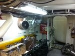
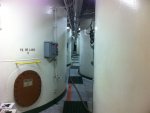
The bearings are definitely not visible from one spot. In the picture the round things in the center are bilge to overhead bulk pressure tanks for dry cargo. They work the same way as a sandblaster. The shaft line that you see in the pic is just under a removable aluminum deck plate walkway. The sides of the walkway are other tanks for fuel water mud oil etc.In the back you should see a universal joint on each side. That's a upward walkway. The u joint is to change the shaft direction. Just behind the engines is a solid fire bulkhead.

I have one senior engineer that wants numbers. Still talking about it.
 

bullethead67

New Member
)

One question though. When the engines have been off for a while, perhaps in very low ambient temperatures, I would expect the bearings to all show a low-temperature alert for quite a while after starting. Could this become a problem? Perhaps the techies will get used to seeing flashing green lights and begin to ignore them? Is a low-temp condition actually serious? Would a non-flashing Green indication be better?

I like the project. Very Picaxable. Best of luck.
Slow changes in temperature are expected. Slow to cool down slow to heat up. We repeatedly have to hold rpms and wait to see if a bearing that was running hot is fixed after a rebuild.

No low temps aren't serious pretty much I thought it would be a good way to identify the difference between a burnt led and a sensor problem. If the led was ever not lit most likely it's a bad led. If it was reading cold while running sensor problem. Possibly the sensor came off.
 

John West

Senior Member
If the engineer wants numbers, it's probably easier than wiring up a bunch of LED's. Get a nice big 2 digit 7-segment LED display and have the PICAXE display the value '88' (to show that all LED segments are working,) unless there is an error. If there's an error (either a failure to read a sensor or an over-temp indication,) the display can flash the number of the bearing with the problem.

If there are more bearings with problems, you can flash the numbers in sequence. One red LED beside the display can be used to indicate overheating of the numbered bearing while one blue LED beside the display can indicate the displayed number has a "cold" or dysfunctional bearing sensor.

The display is simple hardware to hook up and the combination of the display and the two LED's can let even an idiot know the number of the bearing with the problem and provide an idea of the nature of the problem.

That's actually about the quickest display to build (fewest parts) and easiest to read, very reliable, and the software is reasonably easy to implement.

You might want to build up a prototype monitor and display board on perf-board with just a couple of temperature sensors talking to it to use to verify the functions of both the hardware and the software. That much could be done for well under $50. Show that working prototype to the powers that be and they'll have a lot more confidence in the larger project, as will you.
 
Last edited:

manuka

Senior Member
BH67: You may know your needs & situation,but forum posters do NOT. Even my modest marine experience implies "monitoring by walking around " will still be expected in the engine room.

Perhaps an executive summary may be in order You've said 15 yo vessel, ~70m long, 14 crew? (Mmm-implies super yacht ?). Where registered? Where operating (Portugese = Brazil ?), Caribbean? Gulf ? What IS it actually doing -oil/gas? Tonnage (~2000 t?) Rotating crews (significant of course if you are NOT there)? YOUR shipboard role ? Any demarcation/manning issues ? Could DIY add ons influence ship's insurance & servicing schedules etc ? Ah-how about a picture to get our creative juices really flowing !?

Such background knowledge may influence approaches of course. Many decades ago (as a student engaged in summer factory work) I recall rustling up & installing a supervisor approved tank level sensor, only to have the next shift rip it out as "our boy always checks things visually- we don't want your smart ideas". Such sniping is often part of workplace culture, & many forum old hands have probably experienced at least "tin of elbow grease/long weight/muffler bearing/diesel engine spark plug" pecking order put downs...

JW: Well said- in spite of my musing above,a proof of concept prototype can deflate numerous objections !
 

Attachments

MPep

Senior Member
You've said 15 yo vessel, ~70m long, 14 crew? (Mmm-implies super yacht ?)
I would have thought coastal trader, something that could run Trans-Tasman, or do Pacific Island runs.
My own experiences obviously enter into my train of thought.:)

I also agree with JW that making a preliminary mock-up, on the cheap, will prove to yourself and to your bosses, that a PICAXE project is well suited. Of course, the bosses don't need to know about the name PICAXE!! Only that you, BH68, are extremely clever and have a system that can be extended, simply and cheaply. And you made it yourself.
Commercial systems are abound but expensive. Perhaps do a costing of a PICAXE system and a commercial one. Present to your bosses and see how you go.
 

sedeap

Senior Member
Hi Stan:
Seems to be a bulk cargo ship, after take a look on attached pic in post#12

@BH67
Remember, the PICAXE chip is not intended for industrial/reliable grade apps. (Be wise, call it "A Smart MicroProcessor Device" instead of "a PICAXE project")
Maybe you must build one "node" as prototype, showing "in situ" the color LED (standalone), and after get approval, build the rest of the nodes and remote display (maybe embedded in a vessel diagram mural with thru-hole LED over any bearing position)
And for hooking the sensor, magnets are not convenient, I use to fix a nut with (high-temp) epoxy over the (motor, gear, bearing) cover, and then fix the sensor using that nut. (easy to fix, and easy to remove the sensor, if that bearing need be replaced.) The car water-temp sensor bulb (VW or Ford, cheaper) usually well sealed, can do the job.

Best of luck for your project !
 

Dippy

Moderator
Stan para3; absolutely.

MPep para3; absolutely, and it's been said several times from Page2 onwards.

If those 2 things and any electrical/safety restrictions by operators/insurers produce a negative response then that will put the dampers on things.
I hope not as this is a nice project, but I suggest a little research first. WIBNIs are fine but when they meet regs etc. it can fizzle out.

And don't forget your failure Mode Analysis ;)
 

Imre777

New Member
Re: addressing the individual Sensor Boards:
The simplest and most reliable method still is a hard-wired address for each bearing temperature station. This can best be achieved by terminating each of the Address Pins with a 1K resistor on the Picaxe side, and then wiring those pins through a 10K resistor in series to the connector which brings DC power to the board. On the system cable side you can jumper the high bits to the DC power 24 Volts DC assumed) connection. No DIP Switch, no special and unique configuration of any sort required, since the Picaxe will be reading its ID code from the system wiring, not from the PC board.
 

moxhamj

New Member
This is a fascinating thread. I have no doubt the picaxe can do this but the real challenge is working out every possible failure mode.

First a couple of questions. Can you run cables all round the ship? If so, is it easier to run a "star" network, where every node is wired back to base, or is it easier to run a single loop?

I imagine in a practical sense the wire will cost virtually nothing compared with the conduit, mounting it properly, making it robust etc.

Thinking aloud here, if you are running wire and most of the cost is the conduit and the mounting, then easier to use multiple wires and to run power to each node as well.

Next thing - what is the definition of 'hot' in a bearing, and is 'hot' the same whether you are in the tropics in the sun, or skirting Antarctica? I'm thinking that you might need two temperature sensors, one measuring the bearing and one measuring ambient, and take the difference between the two?

Two sensors could also help detect one of the failure modes, which is that a sensor has fallen off or is poorly thermally connected to the bearing, because if there is very little difference between the sensors that should not signify 'cold' but rather 'not connected' (or 'bearing not running').

So you might need 4 leds - 'not running/disconnected', 'cold', 'correct' and 'hot'.

I've got a whole lot more questions, some relating to network protocols and data collision (I have built a number of similar networks but in more benign environments than a ship).

How robust do connections need to be? Is a plug good enough or does it need to be a plug that is sealed to the environment?

How well protected do the electronics need to be - specifically, what sort of IP rating for the case?
 

manuka

Senior Member
Sedeap: Just teasing over the super yacht -I'd spotted the "liquid mud" & "dry cement" containers, but jestingly considered them a cover for bulk supplies of Cavier & Champagne!

Dr_A: Well said. Experience shows tedious insights can be essential when offering solutions...
 

bullethead67

New Member
Couple answers

First a couple of questions. Can you run cables all round the ship
Yes and i can get cable..... but it takes a very long time to get here.

is it easier to run a "star" network, where every node is wired back to base, or is it easier to run a single loop
When going through a bulkhead i am limited to however many spaces are left in the Roks Block its a waterproof cable penetration.

I imagine in a practical sense the wire will cost virtually nothing compared with the conduit, mounting it properly, making it robust etc
Wire runs already in the area. actually wire runs are in every area. ill get a pic

How robust do connections need to be? Is a plug good enough or does it need to be a plug that is sealed to the environment?
Splashproof for the circut board. the engine room gets scrubbed down with bucket and brush. ill check and get pics of other connectors down there.

what sort of IP rating for the case?
I dont know. ill photograph what is installed elsewhere.

And don't forget your failure Mode Analysis
Ship Already meet all requirements and tests for FMA

I also agree with JW that making a preliminary mock-up, on the cheap, will prove to yourself and to your bosses, that a PICAXE project is well suited
I have to agree. until something is seen and works it will get the cold shoulder.

Perhaps do a costing of a PICAXE system and a commercial one
Not needed. commercial systems are touchscreen and monitor everything. They also cost more than a house.

BH67: You may know your needs & situation,but forum posters do NOT. Even my modest marine experience implies "monitoring by walking around " will still be expected in the engine room.

Roving patrol would still be required. This would give warning much earlier than 1 hour ( IF the rounds are getting done) If someone gundecks it and just writes the tems then it could be several hours.

Where registered?
USA

Where operating (Portugese = Brazil ?), Caribbean? Gulf ?
Brazil

What IS it actually doing -oil/gas?
Oilfield Supply

Tonnage (~2000 t?)
2092

Rotating crews (significant of course if you are NOT there)?
Yes...... are you psychic ?

YOUR shipboard role ?
Captain

Any demarcation/manning issues ?
Minimum manning is already in place. it is authorized because we have an automation system that monitors things in the engine room.
You would think bearing temps would be on the required list... me too

Could DIY add ons influence ship's insurance & servicing schedules etc ?
NO for insurance. yes for servicing. Uptime on equipment would increase. I am having trouble convincing others of this though

Ah-how about a picture to get our creative juices really flowing !?
Im stuck in the wheelhouse right now. Ill be here for several more hours. but ill try to get some pics.

only to have the next shift rip it out as "our boy always checks things visually
Each ship has 2 captains. 1 at home 1 on board. Yes that could happen. and yes it does happen.

JW: Well said- in spite of my musing above,a proof of concept prototype can deflate numerous objections !
Ok proof of concept prototype. I saw a temp display on the internet but it was for 1 sensor. and i would need 3 digits. It would have to be in Fahrenheit. Lead engineer is American as is vessel managers.

What is hot?
there is disagreement on this too. appx 140 is getting hot and 170 is really hot. 200 is cooked. ill need to contact Cooper bearing and get a specific range.
 

bullethead67

New Member
Prototype

OK hows this for a proof of concept=

Serialpower network

For 8 bearings

8 RGB LED

1 display for name and temp

2 buttons for scrolling through bearings. on display

1 button for lamp test (holds each color for 3 seconds) (sensors tested by automation test kit, its a annual thing boats do)

no flashing leds except red (theyre annoying)

Modes for LED= blue cold, green warm, red, flashing red (no temps yet)

ID able to be set by user. jumper, DIP, selector etc.

Power taken from 110VAC using a DC power supply (no batteries, that wont help sell it)

Prototype will stand alone and will not pass through bulkheads
 

manuka

Senior Member
The esteemed (& PICAXE friendly) DS18B20 measures temps. from -55°C to +125°C (-67°F to +257°F), but reads out in Celsius. It's assumed your "110,140,165 etc" are in degrees Fahrenheit, & although it's easy enough to convert values, best you first clarify!

FIFO (fly in fly out) crew traditionally totally forget their day job when away back home, so who will make this prototype,& where & when ? As captain you'll be too busy when on duty for such proof of concept work...
 

John West

Senior Member
manuka:
From BH67
I saw a temp display on the internet but it was for 1 sensor. and i would need 3 digits. Lead engineer is American as is vessel managers.
We're working with Yanks in charge, so Fahrenheit it is, but it appears in this case that whole-number conversion from Celsius would be close enough, (although it might bother some of the more astute idiots seeing digits jump by 2, so I suppose we need to have the extra bit reads and conversion done at that.)

Carefully thinking through the display format so everything is simple to build and code, quick, clear and easy to read (by idiots and American engineers) and informative, is one of the most important aspects of the project. And kinda fun to think through and plan out how to most effectively implement as well.

I always like the challenge of working on human interface stuff in order to make it really user friendly, as the technical end of a project is often pretty cut and dried.
 
Last edited:

hippy

Technical Support
Staff member
And don't forget your failure Mode Analysis
Ship Already meet all requirements and tests for FMA
I think the point there was adding the monitoring would affect things.

FMA is quite a wide field considering what could fail, how, why that may be, along with potential consequences and mitigation of failure consequences.

It's very easy to imagine a mere monitoring system won't - even can't - have any adverse effect on anything but FMA is there to analyse that in respect to everything which could possibly go wrong. What for example happens if the power supply in the master control panel fails; could it short out the supply bus bars ? What happens if a cable to a bearing monitor wears out or is stressed and a short occurs ?
 

bullethead67

New Member
PICS

IMG_1926.jpg
Standing between main engines facing aft. shaft is covered by yellow guards. bearings are green.

IMG_1927.jpg
Standing in doorway. looking to Stbd. you can see the bearings under the deckplates
 

bullethead67

New Member
IMG_1928.jpg
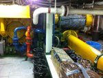
Tank room facing aft Port side. wire loom overhead

IMG_1930.jpg
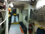
Passage to steering compartment. shaft is at upward angle. notice wire loom on right

wire looms are everywhere
 

Dippy

Moderator
Oooh that's wiry. ;)


Hippy has expanded on my FMA point very well. It doesn't matter what has gone before, it matters how YOUR bit may affect the system and whether YOUR bit is safe.

Have you approached the owner/operator/Inurance Co with your proposal yet?
If you aren't qualified in Electronic/Electrical engineering they may say "No way me Hearty!".
It's a terrific project and I'm jealous, but without their go-ahead we may be wasting a lot of time.
Do a proposal including costs/savings to get an initial response, then if OK you'll have to present a working and tested prototype and wait for the "Yes please Matey, and here's a blank cheque".
Get some feedback before going up a cul-de-sac.

In any event you need to practice and test small-scale on the bench.. 'running before we can walk' and all that.
Where I work we have qualified and experienced engineers and designers and it takes literally weeks/months to carry out testing by qualified engineers and technicians - I thought I'd just mention that to put it into perspective. And that's for land based vehicles.

Whatever happens this will, at least, have been an education and I sincerely wish you luck with it.... Don't lose heart :)
 

John West

Senior Member
A couple of thought:

Almost every circuit can be built so there is no danger of overheating or causing problems back upstream from any failure mode. Often it requires no more than a few resistors and or hardwired resettable fuse. This is a good project to implement such circuitry on.

It appears the bearing housings are unmarked, though I'd expect there's some way of identifying which is which. A nice big number stenciled on the individual housing or the local PICAXE sensor box would make bearing ID quite clear.

This project is a good idea, and its implementation with PICAXE's is an excellent choice. The actual data gathering and resulting display is quite easy for a PICAXE. The real project will be in implementing all of the reliability and circuit protection features. It's more a "think it through and build it well" sort of project than a "can this be done?" sort of project.

I know nothing of shipboard electrical wiring regulations, but if all parts of the system are low level signals and isolated from the rest of the ship's systems (other than power) I wouldn't expect there to be significant difficulties with any sort of insurance or regulatory requirements. Making it a free-standing system is key to that. Sometimes simply using an AC plug to connect to the power source instead of hard-wiring the power into the building (or ship) wiring removes all of (or most) red-tape and regulatory concerns.

A simple clip can then be added to an AC outlet to reliably secure the power plug while still avoiding red-tape. (I've had to deal with agencies from UL to the DOD here in the US and have worked hard at developing techniques for avoiding red-tape. :))
 

moxhamj

New Member
Those photos are brilliant!

I can see some great solutions.

1) I did a quick google for "bearing temperature sensor" and there are some very professional looking units that have thermocouples. Some have cables with flexible metal shielding and they are spring loaded for clicking into a hole. I might leave it to the brains trust here to discuss LM35 vs other sensors vs professional thermocouples, but I'd be inclined towards the latter. Which then raises the question - how do you interface a thermocouple to a picaxe?

2) Earlier I mentioned IP ratings for cases. You have a perfect example of an appropriate cabinet on the photo "Tank room facing portside". And I think there might be another in the "where shaft ends" at the top right of the photo. These cabinets have a rubber seal and they have hinges and they usually have a key lock. They can be plastic or metal. They are airproof so that means you can use any sort of connectors inside, and dip switches and other components without having to worry about corrosion and rust. Take a look at the cabinets and I'll bet they have waterproof glands at the bottom where the cable goes in. It is a fairly standard way of making things. So in the bottom you might have four holes - power, data in, data out, and the cable to the sensor. On the inside of the cabinet you can then wire things up with any sort of plug. You might like to have a board with plugs on it so you could quickly remove a board and replace it if it is faulty. On the front of the cabinet might be your three lamps and I think on that first photo is a perfect example of a red and green lamp. Make them big so you can see them from a distance.

3) Maybe build things in stages. Build a box with lights and a picaxe and a thermocouple and light up three lamps as it warms up. That in itself ought to be very useful.

4) Then look at the data side of things as a separate project.

Re power, there are several options. Local transformers on a din rail inside the cabinet. Local wall warts (assumes mains power nearby). Or local regulation.

One solution is 'power over ethernet'. cat6 cable has 8 wires so you could use two for RS485 Tx (data from the base station saying 'give me a reading'), two for Rx (shared bus but only one node is going to reply at a time), and two for power. Only catch with that is the resistance of the cat6 cable might be a factor, but you can always do clever things like run 24V DC on the ethernet cable and use a local switching regulator to get 5V. cat6 is great because all the plugs and sockets are easily available. So inside a cabinet you might have two cat 6 cables and they either go to your board, or say you removed that board for servicing, you could use a cat6 joiner to temporarily plug the cables together.

Having said that though, it may be easier to build the first one with local regulation. It depends if you have a standard power outlet near each location or not.

You can use a number of data systems including two wire solutions as mentioned previously. There are some advantages to sticking with standards. RS232 is a good standard for a 'star' network, and RS485 is a good standard for a single 'party line' network. The chips to convert picaxe to RS232 or RS485 are less than a dollar each. Keep the baud rates slow (ie 1200 baud) and you can go many kilometres with no interference.
 
Last edited:

graynomad

Senior Member
The temp range would be around 15 to 100 C
You don't need thermocouples for that range, they may or may not be better but any temp sensor will cover that.

As for the physical layer, in an industrial environment like this I really think the only viable option is RS485.

IMO you cannot use SerialPower as is, connecting uC FET IO pins to 70m of cable in an environment like that is not a recipe for reliability.

However...I think you could still use SerialPower with RS485 transceivers (wired differently to the norm) and power over the cable. That would give you the existing (presumably reliable) software and industry-standard PHY layer.
 

bullethead67

New Member
Meeting

Well im off the ship. I was supposed to meet with a manager. Never happened. I cant say im surprised everyone here is stretched very thin.

Im going to go ahead and build a 8 sensor unit out of pocket. Not just because i want the project to have a prototype but also because my head is reeling with all the possibilities on board and i dont want to get sidetracked.

I did get concerned about the serialpower not being a reliable solution. as for RS485 i do know the basics but not on a manufacturing or component integration level.
 

John West

Senior Member
As for the communications methodology, the differential comms of RS485 are far better in an industrial noise environment such as is found aboard a work ship. The communications chips are readily available and Graynomad's advice is right on target. We PICAXE'rs seldom need to use RS485 for our home communications projects, but in industrial environments it's the standard for a very good reason.

Bullethead67, just click on my name on this post to send me a PM (private mail) if you'd like some RS485 chips to try in your prototype.
 
Last edited:
Top