If you were just starting out...........????

pjl83

Member
There's a Maplins round the corner from work in Nottingham. I pop in tomorrow.

I haven't checked out the board, I wasn't aware that I could do anything without a circuit to test. :confused: I was just going on page 44 of manual one "testing the system" where it says that I need an led circuit to test?
 

eclectic

Moderator
There's a Maplins round the corner from work in Nottingham. I pop in tomorrow.

I haven't checked out the board, I wasn't aware that I could do anything without a circuit to test. :confused: I was just going on page 44 of manual one "testing the system" where it says that I need an led circuit to test?
PE, then
View
Options

e
 

Attachments

pjl83

Member
hmmmm......

ERROR! Serial port error - port not present or already in use.

Any ideas? I installed the driver from the CD and XP recognised the new hardware?
 

eclectic

Moderator
hmmmm......

ERROR! Serial port error - port not present or already in use.

Any ideas? I installed the driver from the CD and XP recognised the new hardware?
First, very quick response.
PE > view > Options > Serial

AND, did you plug in the USB cable
BEFORE you started working?

e

And, install the driver from the Picaxe Home-page.

It'll be more up to date,
 

Attachments

pjl83

Member
aha...

I did the serial port test and there was 0.05 volts with the virtual led off and 4.8v with it on across the serial input pin and 0v. From what it says in the PE I think it's correct. I wish Maplins was open 24hours........... or that Asda sold 330ohm resistors :rolleyes:

Thanks
PAul
 

eclectic

Moderator
aha...

I did the serial port test and there was 0.05 volts with the virtual led off and 4.8v with it on across the serial input pin and 0v. From what it says in the PE I think it's correct. I wish Maplins was open 24hours........... or that Asda sold 330ohm resistors :rolleyes:

Thanks
PAul
So, err, is it OK now?

e
 

pjl83

Member
I assume so? Thanks for the help.

When I originally clicked the "check firmware version" this is where I was getting the error message. I downloaded the driver from the PICaxe site as you suggested and then did the serial port test which seemed ok. Now when I check the firmware version it recognises the hardware as "Firmware version 9.2 (PICAXE-08M Firmware Version 2).

So I think it's fine?

Thanks again ;)
 

hippy

Technical Support
Staff member
The serial port and driver would seem to be okay. You can try a simple download to check things out ...

#Picaxe 08M
#Terminal 4800
Do
Pause 2000
SerTxd( "I'm Alive!", CR, LF )
Loop

For LED's, you can often use higher than 330R if you've got other value resistors, even a couple of K, and you can parallel the R's to reduce the resistance. You might only get a dim glow but it's another step in the right direction.
 

pjl83

Member
Thanks hippy, I have the resistors now so I'll build the circuit up tonight and have a play with some flashing sequences.

;)
 

John West

Senior Member
Is it reasonable to run two LED's in series and dispense with the resistor? Seems like it would keep the current down yet still light up the LED's to a reasonable level? Anyone try that yet?

BTW - I must admit that I'm looking forward to getting socks for Xmas this year. I already have lots of electronic goodies to play with, but my feet are getting cold. I guess I'm finally old.....
 

hippy

Technical Support
Staff member
I believe that in theory it is possible and perhaps also in practice though the theory may also suggest it's not a good idea.

If the voltage into the LED matches Vforward you should be fine, as long as Iforward is below the PICAXE (20mA-25mA) maximum. The chance of the voltage being absolutely right are probably very low; too low and the LED doesn't light, too high and there's a mismatch with higher current flowing but as long as the current remains below the PICAXE limit you should still be okay. In this case you need to match the voltage to 2 x Vforward. I'm not an electrical engineer so that's only my understanding of it and there may be more to it than that.

That's for a permanently lit situation. It gets more complicated when pulsed or PWM'd.

It's easier to play safe and use a resistor.
 

manuka

Senior Member
I've seen this breadboarded for quick IR output boosting-with the user aware it was a suspect practise. As IR LEDs can be briefly pulsed at high power, it made more sense to drive via an NPN transistor.

FWIW classic LEDs were assumed to draw ~10ma when used just for "power on" status, & could thus draw more than typical circuitry itself. This can mean bad news for battery life! However modern LEDs are increasingly so bright (Haitz's Law) that their currents can be wound down to under a mA. Forget classic 330 ohms, since on a 4.5 V (3 x AA) supply it's typical now to specify at least a 1k dropper, with even as high as 10k still giving decent light output. I've a swag of ex. Xmas light red LEDs here that are positively evil in their brightness at just a mA, and a blue needed several layers of masking tape over it for quick dimming!
 

Attachments

Last edited:

Dippy

Moderator
I agree with BB, don't do it.

You could probably get away with it when you are doing low duty modulated stuff. And LED Vf increases with current/power/temp . Not a lot of people know that. Stan's mate got away with probably for those precise reasons. (I just knew we'd have a photo of a breadboard :) )

But it could end in tears if it went wrong. Heat is the killer.

The areas which people should include in their calcs are:
1. Driver limits (current / power)
2. V supply
3. LED If.
4. Led Vf
5. - and when upping the power study the LED's Vf vs If. It can change a lot and can painfully provide some crude self-regulation at the limit.
6 - and ultimately the supply limits too.
 

inglewoodpete

Senior Member
Is it reasonable to run two LED's in series and dispense with the resistor? Seems like it would keep the current down yet still light up the LED's to a reasonable level? Anyone try that yet?
Provided you choose the right LEDs, you can put 2 in series with a suitable current limiting resistor.

When using a regulated supply, good results with 2 series LEDs and 1 series resistor are achievable. But when using a 5v regulated supply, you probably have a higher input voltage available and could use a buffer transistor and a chain of LEDs.

Note that high-brightnes LEDs usually drop more voltage when operating, so it may not be possible the put 2 of these in series with a 5v PICAXE supply.

The difficulty is determining the voltage drop and the current and therefore the resistance value to use. It depends on the supply voltage and type. If using batteries, then the voltage will drop during their life. If using 2 x 2.0v LEDs, you are left with less than 1v to drop across the resistor.

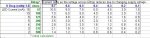
The attached jpeg snip from Excel highlights the problem. The first table calculates the size of dropping resistor when using 2 LEDs having a forward voltage of 2.0v+2.0v=4.0v and a 5.0v supply, against several desired LED currents. The second table shows what happens to the LED current as the supply voltage drops from 5.0v to 4.0v: as the batteries age.

Using the example of a desired current of 10mA with fresh batteries (assume 5.0v). As the the batteries age down to, say 4.2v, the current through the LEDs will have dropped to 2.0mA - a substantial reduction in LED brightness.
 

Attachments

John West

Senior Member
Thanks for the analysis, Pete. I've copied it for handy reference. My thought was that if no resistors were handy (not a problem in my case as I have an overabundance of them,) that the full power voltage drop of two typical LED's in series would be enough to limit the output current from the PICAXE to a safe value for testing.

A current limiting resistor is always the reasonable solution to the problem of differences in LED volt drops and their change in voltage drop with temperature - as long as you have one handy of an appropriate value. But if you don't, a couple of LED's in series might just get you by.
 
Top