Best Stepper Motor Commands

mikemwa

Member
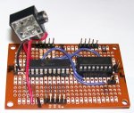
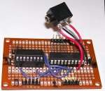
I got my circuit from the solderless breadboard to a regular soldered perfboard(s). The motor will not run right no matter what I do. It will do nothing but jerk and stay in the same position. I have arranged the wires on the motor everyway possible a number of times. I have quadruple checked the components and soldering until I’m going cross eyed.
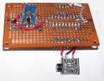
I have LED’s between the 20M outputs and the 293 inputs to see what is going on. When I remove the motor connector from the board the LED’s light up normally like they did on the solderless breadboard. When the motor is connected the LED’s light up erratically just like the motor is running.
I’ve been trying to get this to work for 3 days now and I am getting nowhere.
Any suggestions or are there any tests that I can do to find out what’s going wrong.

Mike
 

eclectic

Moderator
@Mikem

1. It's been working on breadboard. We know that.

2. It's NOT working on perfboard.

I Genuinely don't know why.
I have NO experience of Perfboard.

3 My only suggestion at the moment.

Get some Stripboard / Veroboard.

Wire it in the configuration I've shown in the picture.

Then COPY the Breadboard wiring.

e
 

Attachments

papaof2

Senior Member
Give us pictures of the actual board you're using.

Possible problem areas:
- an off-by-one connection to one of the chips
- an open/short on the board.
- a bad solder joint that passes enough current for an LED but not a motor.

John
 

mikemwa

Member
Another curiosity I just noticed is on the other board I had another switch to simulate an input from the machine that this will be connected to. Once using the switches on pins 5-9 to position the Mic I would hit the start switch on pin 5 to start the sequence. It would move to the first position and then I would push a button on pin 4 to move to the next position and so on.
On this board after I position the Mic and hit the start button it will move to the first position. If I hit the start button again it will move to the next position and so no. It did not do this on the other board. At this point I do not have a button on pin 4.
So I guess 1 question I have is do unused pins need to go high or low? I did not do this on the3 other board and it works fine.

Mike
 

eclectic

Moderator
Mike.

If it DOES work on breadboard, but doesn't work on Perfboard,

then I've only got one suggestion.

Post #82 STRIP board.

e
 

mikemwa

Member
I grounded all unused inputs and added the switch to pin 4 like I had with the solderles breadboard. Everything else is working like before except for the motor is still not working right when connected. I increased the delay so I could see what's going on. With the motor not connected the LED's on pins 14 - 17 light up as they should. With the motor connected and pressing the buttons 6 - 9 this is how the LED's light up in general.

14 15 16 17
X....X
X....X
X....X
X....X
X....X
X....X
................X
...........X
X....X
X....X

It's not like this 100% of the time. It seems to change sometimes.


Also when I put LED's in place where the motor goes it's working OK.
 
Last edited:

mikemwa

Member
This is getting very frustrating. I've been trying to get this thing to work for a week and a half and it's just not happening. I cannot get the motor to work right. If I hook led's up to where the motor goes they go in sequence fine. If I hook the motor up with the 7.5 volts disconnected from the L293D the motor works but is weak and the 4.5 volt regulator gets hot. Then when I hook up the 7.5 volts the 4.5 volt regulator doesn't get hot and led's flash in some goofy sequence and the motor grabs but will not turn.
Are there some other components I need to hook up to this?
Mike.
 

BCJKiwi

Senior Member
Looking at the last circuit posted, there seem to be no capacitors on either regulator or on the AXE supply.

Motor loads will be short and sharp pulses. A large cap on the Motor reg output could help in addition to the data sheet input and output caps on both regs to stabilise them.

Motor circuits are noisy so there should also be a filter on the AXE supply as per the Picaxe manual recommendations.
 
Last edited:

eclectic

Moderator
Thanks BJC.
I need my specs cleaning!

This datasheet
http://www.fairchildsemi.com/ds/LM/LM317.pdf

shows 0.1 uF and a 1.0 uF

On say a 28X Picaxe board, AXE020, there is also
a 100 nanoF ceramic and a 10uF electrolytic.

So, as a start, add the above four capacitors.

A genuine question from me:-
I can't see any harm in adding a couple more capacitors, of say
47uF, and 220 uF. (Assuming correct voltage rating).

e
 

mikemwa

Member
I added the caps to the regulators. It's working much better now. Radio Shack did not have any 1uf caps. So for now I am using 6uf caps temporarily until I can get the 1uf. Is this going to be a problem until I can get the others?
 

BCJKiwi

Senior Member
I'd just leave the 6uFs in place. More won't hurt. In fact, as suggested earlier even more might be beneficial on the reg output side for the motor.
 
Top