Avoiding electrolysis/moisture sensor.

Captain Haddock

Senior Member
If I use an 08m2 for a moisture sensor and use C.4 & +5V to readadc briefly every so often and set C.4 as a high output in between times would I be right in thinking this would reduce galvanic corrosion of the probes (stainless mig-wire) to a minimum? Would a resistor on C.4 be needed to limit the current or would that just mess up the readings?
I will be using hi2c for an RTC so C.1 & C.2 are used and still need another output for switching so C.0 will be used for that.

I am wanting to check the dampness of a growbag and switch a pump while we are on holiday.
 

eclectic

Moderator
A genuine question for the experts:

If you considered the electrodes as disposable,
would a few days/weeks be that important for corrosion?

e
 

Svejk

Senior Member
Another way to measure the moisture is to use the capacitive touch sense of 08M2. Give it a go.
 

Captain Haddock

Senior Member
I'm reconing if the probes are only -/+ volts for a few seconds every few hours then both +V the corrosion should be so small to not worry about over the space of a month or so.
Touch sense is an interesting idea though.
Cheers all.
 

mrburnette

Senior Member
If I use an 08m2 for a moisture sensor and use C.4 & +5V to readadc briefly every so often and set C.4 as a high output in between times would I be right in thinking this would reduce galvanic corrosion of the probes (stainless mig-wire) to a minimum?
My understanding of galvanic corrosion is that generally either dissimilar metals are involved or a current sufficient to induce the metal to form metallic ions must be applied. Stainless steal is rather corrosion resistant , so the soil pH is (probably) not of too high a concern. In regard to the testing current for determining the soil resistance, why not alternate the polarity on alternate reads? For example use C.4 and C.1/C.2 and configure on read where C.4 is ADC and the other pin is set as an output HIGH and then on next read, flip the functions... in the off period, tri-state both pins.

- Ray
 

hippy

Ex-Staff (retired)
If I use an 08m2 for a moisture sensor and use C.4 & +5V to readadc briefly every so often and set C.4 as a high output in between times would I be right in thinking this would reduce galvanic corrosion of the probes (stainless mig-wire) to a minimum?
No. An output high will produce slightly less than +V on a pin so there will still be some current flowing through the sensor dues to potential difference.

You could add one or more diodes at the +V end which will drop the voltage at that end lower than the output high voltage and the diodes, being reverse biased, will prevent any current flow when output is high.
 

Anobium

Senior Member
I have used a simple probe without issues for nearly two years. The probe is a piece of strip board.

I am travelling at the moment but seacglh on ' anobium cellar water'. I think all the information is in the posting.
 

joely87

Member
Hi All,

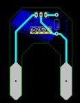
I am looking at developing a moisture meter. I assumed a simple potential divider would work but having some issues with unstable ADC. For a start I would like to just develop a reliable probe and then one it is stable I will be begin looking at solutions for electrolysis. I have made a PCB that has too big pads at the end of each probe, and then a spot for an optional resistor between ground and ADC line. See attached.

Moisture Meter small.jpg

I then used a multimeter and measured the resistance between +V and ADC, and got a value of around 3M (without watering for approx 1 week) and 50K after watering. So I initially decided to put a 2.7M Ohm resister between ADC and ground. My thinking was that if the plant hadn't been watered for around a week the soil resistance could be approx 3M and therefore the ADC should be around 128. But i thought it would be better to get more use of the ADC resolution if i lowered the resister value and therefore if the soil resistance was around 3M the value could be lower than 128.

So I decided to use a 1M resistor and here are some my calculation to verify my thinking is correct:

Dry (2 weeks)
SoilRes = 4M SetRes = 1M
MoistADC = Vcc x (SoilRes / (SoilRes + SetRes)) x 256 / Vcc
MoistADC = 5 x (4M / (4M + 1M)) x 256 / 5
MoistADC = 51.2 = 52

Needs water
SoilRes = 2M SetRes = 1M
MoistADC = Vcc x (SoilRes / (SoilRes + SetRes)) x 256 / Vcc
MoistADC = 5 x (2M / (2M + 1M)) x 256 / 5
MoistADC = 85.3 = 86

Wet (10 min after watering)
SoilRes = 50K SetRes = 1M
MoistADC = Vcc x (SoilRes / (SoilRes + SetRes)) x 256 / Vcc
MoistADC = 5 x (50K / (50K + 1M)) x 256 / 5
MoistADC = 243.8 = 244

The problem I am having is that even when the probe is out of the soil I am still getting a reading jumping between 20 - 80 and it should theoretically be 0. I am using a LM317 circuit to step a 9V wall supply down to 5V. I have read about using a capacitor between ground and ADC to filter some noise but unsure how to calculate an appropriate capacitor.

Cheers,

Joel
 

Dippy

Moderator
Post your schematic so that ambuigities are removed.
You could be suffering from high impedances upsetting ADC requirements.

And, as an aside, do you unerstand the idea of using AC to reduce corrosion problems?
 
Top