Virtual Breadboard continued
The Virtual Breadboard program is predominantly using GIF images for most of the components.
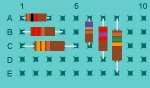
Only the wires and resistors are calculated and drawn on the fly.
Based upon my own ideas and those put forward by Manuka and Dr-Acula, the following constitutes a list of items to add or adjust:
• Various colour LEDs
• A "fatter" transistor - also add TO-220 to the TO-92 outline (covers 1A 7805 etc then as well)
• 180 rotating DIP IC’s
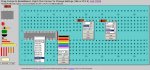
• Switch – 2 terminal pushbutton, 2 terminal toggle, 3 terminal toggle
• Terminal strip in 2,3,4,5 holes
• Electrolytic cap in 2 or 3 sizes, 2/3/4 hole span
• Tantalum cap in 2 sizes, 2/3 hole span.
• a battery – as 4.5V
• a crystal
• a 7 segment display – to add under the IC’s listing
• LDR
• Thermistor
• Piezo buzzer/speaker
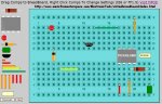
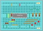
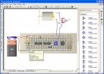
The attached diagram gives an idea of what expansion and improvements I have in mind. See how it goes with getting the above done in forthcoming evening (but nothing tonight – its birthday time
")
)
Adding a device involves adding gif images to the image folder, adding to the various scripts to incorporate the pull down menus, defaults, pointers to images, etc. This typically involves working on 4 out of the 9 javascript files from the original program package.
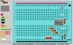
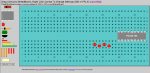
For switches, batteries, placement needs to be thought about. Maybe the answer is to have a clear area at the top and bottom of the breadboard where these can be deposited. Will require some thought on placement scheme while I work through other add-ins.
Once I have assembled the program to include the above mentioned features I can put it on Manuka’s website for all to access and send a copy back to the original author.
Batteries and switches will need to be side view as opposed to the top view of other components.
If others here have top view images of LED’s all to the same style and size in various colours, eg Red, Green, yellow and blue PM me or post them here to save me time searching.. Minimum image size as say 22 x 22 pixels, larger okay as I can scale them down