433mhz transparent wireless data module
- Thread starter yamato96
- Start date
I am playing with the Hope HM-TR module at the moment
www.hoperf.com/pro/HM-TR.html.
They are configured from the PC via RS232 and you can chose whether you want to use the 232 or TTL version when you purchase them. They are as simple as using the serin and serout command for communicating with picaxes.
Hooter
www.hoperf.com/pro/HM-TR.html.
They are configured from the PC via RS232 and you can chose whether you want to use the 232 or TTL version when you purchase them. They are as simple as using the serin and serout command for communicating with picaxes.
Hooter
BeanieBots
Moderator
Probably worth checking what levels your PC puts out.
If it's a laptop, chances are it's 5v logic levels.
Personally, I'd go for TTL. It would be much easier to interface to PICAXE and if you need 232 levels just for PC configuration then it should be possible with just a few resistors (and maybe a diode).
One thing to check is if the TTL version requires inversion. If it does, PICAXE interface will still be simple but connection to a PC would require inversion. It's quite easy to make a TTL/232 interface (MAX232) if you get the TTL version and need inverted 232 for your PC.
Hooter is our resident "Hope" expert, but just reading the specs I suspect it is going to be easier to program from the computer than from a computer to a picaxe to the device, so that means RS232. You can do a formal RS232 to TTL translation with a single chip called a MAX232. These vary in price between $1 and $7 - you can get 10 of them for $10 including shipping from http://stores.ebay.com.au/Thai-Shop-Etc
Or you can do a poor mans version, which is the same as the download circuit for the picaxe with a 22k and 10k resistor. Proper RS232 goes between -12V and +12V with a valid high 3V to 12V and low -3V to -12V and 0V is not a valid value. Shortcut RS232 which will work into a PC allows 0V to be a low.
Bear in mind that the MAX232 chips invert the signals which isn't a problem if you go from a picaxe to Max232 to Max232 to picaxe, but might be if you only had one MAX232 in the loop.
Hippy - these modules use FSK and say they are "transparent". They also come in a range of frequencies. I wonder if this could open up the possibility of programming a picaxe via radio?
Dr_ac: "Transparent" is such a general term really. It just means the device will do some work for you.
I think if you 'scoped the Serin/Serout of he PICAXE during pogramme download you'd see the problems, especially at the start.
The 5mS Tx/Rx switchover time of that module is far too slow anyway. If it were full duplex then you may be getting somewhere.
I am pretty certain, and I mentioned it to hippy yonks ago, that a suitably programed PIC as the radio interface/data buffer/emulator at each end could do the job.
eg: PC -> PIC(Data buffer/emulate PICAXE download) -> RadioTx >>>> RadioRx-> PIC(Data Buffer and PC emulator) -> PICAXE.
I know that sounds like overkill, but if you looked at the lines using a scope you'd see the timing issues and the initial bit that I'm on about. Otherwise some bright spark would have done it ages ago using a basic Radio Modem.
I'd love to have a go at it myself, but it's time. The Rev-Ed boys could do it in 10 minutes as they know all the timing protocols etc. Well, maybe 20 minutes including coffee.
If there is a simpler way I never heard of it. Maybe some genius has done it... (i.e. 'DONE it' rather than theorised into a pint of beer.)
After reading ur repliews and since my idea is to set up a pc to picaxe rf datalink/picaxe to picaxe rf datalink in a modular way, maybe the best choise is to order one version in TTL and other in RS232, earning more teck capablities and knowledge in implementing my projects.
is it harder to set a simple serial comunication with rs232 rf module and picaxe? Can i still have the transparent rf link feature with the RS232?
Other way is two TTL modules, and instead of interface pc to rf by max232, i use a picaxe and keep it simple and cheap.
better looking in datasheet, and it seems to me that the core hardware in the module its the same in TTL/RS232 vers. and just aded max232 soic ic or similar ond the board 4 rs232 vers.
Last edited:
I wouldn't recommend putting a PICAXE between the RF and PC, it just complicates matters considerably. You'll be much better off with an RS232 to PC, or a MAX232 or some simple 74xxyy logic gate buffering between the RF and PC if you want to only buy TTL versions.Other way is two TTL modules, and instead of interface pc to rf by max232, i use a picaxe and keep it simple and cheap.
If you buy one TTL and one RS323 you can probably modify the RS232 version by removing the on-board MAX232 SOIC if you ever need to ( I haven't looked at the data sheet ).
I agree with hippy - keep it as simple possible. If you start getting overcomplicated you'll spend more time on this Forum than on your project.
However, with my fat fingers I wouldn't recommend removing an smd component. Certainly any warranty would disappear. As would the pcb tracks if you mess up - and the probability is high that that will happen.
Now I admit I haven't tried every PC ever manufactured, but I have yet to find one (under 4 years old) where a short-length serial to PICAXE/PIC link won't work using a simple level shifting (like PICAXE download) or simple transistor inverting circuit (2 transistors + a couple of resistors).
If my wallet was unlimited I would buy 2 off TTL types and 1 off RS232 type. Belt and braces really and I don't know much these things cost. After all, you'll probably have another project needing RF ... or you might break one, so it won't be wasted. But it's your money.
I did some proof of concept work on that ( when I ended up wiping 18X's clean ) and it is possible but wasn't brilliantly reliable, and this was over a straight serial ( no break signalling ) hard-wired link.I am pretty certain, and I mentioned it to hippy yonks ago, that a suitably programed PIC as the radio interface/data buffer/emulator at each end could do the job.
eg: PC -> PIC(Data buffer/emulate PICAXE download) -> RadioTx >>>> RadioRx-> PIC(Data Buffer and PC emulator) -> PICAXE.
The most reliable mechanism is a complete download into a transmitter, have the transmitter send that to the receiver, and have the receiver program the target PICAXE. The problem there is that the Programming Editor will report everything worked perfectly even though the receiver hasn't even started programming.
It's a lot of work and effort though for little gain.
"The most reliable mechanism is a complete download into a transmitter, have the transmitter send that to the receiver, and have the receiver program the target PICAXE."
- that's what I meant. That is what I suggested before.
The PIC emulates the PICAXE download , flashes/EEproms the programme dumbly, then sorts out the comms to another PIC via RF. The second PIC flashes/Eeproms it and then 'pretends' to be the PC+Editor to your target PICAXE.
And, yes, the requirement is so minor that was why I didn't try it.
Ditto the idea about transferring programme to little box and then waving little box at PICAXE to reprogramme it on-site. All very nice, but spending days/weeks designing for a market of 2 sales is a bit inefficient.
Yes, the bit about the editor is true, so not ideal. But your second PIC/PICAXE combo could compare data and if using transceivers report success back to first PIC and a little LED (via a resistor) could light.
Ah, even more complication and expense, and all for 2 sales. And no-one would buy it unless it cost under a fiver as they're so tight. So, no I won't bother.
Anyway, enough asides, if anyone wants to discuss it further start a NEW thread - meanwhile back on this thread.....
Yamato96 - Its as easy as Serout from one pin of the Picaxe to RX of the Hope-HM-TR and
from the TX pin of the HM-TR to an input pin of the Picaxe and use Serin to capture the data.
The HM-TR automatically switches back to receive mode after transmission is complete.
You can also use an additional Picaxe pin to send the HM-TR to sleep to conserve power.
Hooter
from the TX pin of the HM-TR to an input pin of the Picaxe and use Serin to capture the data.
The HM-TR automatically switches back to receive mode after transmission is complete.
You can also use an additional Picaxe pin to send the HM-TR to sleep to conserve power.
Hooter
their pin labelling had me stumped for a whole afternoon! DOH!
RX is DATA INTO THE MODULE not DATA BEING RECIVED BY THE MODULE ARRGGGGHHH!!!
Other than that they are good fun")
I have 1/2 dozen of them happily passing data around the workshop at the moment - nothing useful just flashing their little leds LOL
RX is DATA INTO THE MODULE not DATA BEING RECIVED BY THE MODULE ARRGGGGHHH!!!
Other than that they are good fun
I have 1/2 dozen of them happily passing data around the workshop at the moment - nothing useful just flashing their little leds LOL
Re: "their pin labelling had me stumped for a whole afternoon! DOH!"
Actually, that sort of thing is a mistake all of us could/would make. It is the difference between the theory of getting something working and actually getting it working. We would all find a writeup (with photos) extremely helpful!
Actually, that sort of thing is a mistake all of us could/would make. It is the difference between the theory of getting something working and actually getting it working. We would all find a writeup (with photos) extremely helpful!
Interesting high power 500mW transceiver module from Hope at http://www.hoperf.com/pro/RFM12BP.html - particularly interesting given the very high sensitivity values for the receiver. The programming protocols look complicated though.
Does anyone know the price - I couldn't find it on the website?
Does anyone know the price - I couldn't find it on the website?
HopeRF units arrived safely & under investigation. SMD fine print reveals an on board Atmel ATMEGA48 micro in fact. Stay tuned!
Attachments
-
 39.2 KB Views: 68
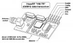
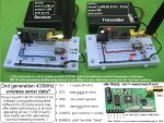
Have just fired up Hooter's HopeRF HM-TR FSK transceiver pair (working into a couple of 08Ms), which fit nicely on the usual small breadboard OK. The RS-232 types supplied have a Max232 on board already- as shown in the pix below. The config. setup (which runs under even W98 on an old serial laptop) is very nifty,& my usual PICAXE header pin programming lead did serial pins 2,3,& 5 double duty OK when links were made. Changes (such as the 9600-2400bps) stored away readily on the Hope units. Two SMD LEDs very usefully show activity - green for signals being received, red tx etc. Anticipatory hand rubbing was in order!
However the transmitter power setting was immediately annoying, as the maximum seems only 0dBm (1 milliWatt), with changes (such as -10 dBm =100 µW) only for LOWER powers. Every 3 dB increase represents roughly doubling the power, which means that 3 dBm equals roughly 2 mW. For a 3 dB decrease, the power is reduced by about one half, making -3 dBm equal to about 0.5 milliwatt. ARGH- this is quite pathetic given the ISM band allows 25mW legally, & most ASK "garage door openers " are ~10 dBm (~10mW). Predictably hence 0dBm made for pretty trivial ranges, with ~100m LOS,when connected to the supplied rubber ducky, being all I could manage to hear even on a sensitive scanner.
Additionally frequency settings (such as 433.92MHz) do NOT equate to the correct output noted on the scanner, which in this case was 434.105 MHz. I suspect one of the units is defective as well (Hooter- any insights?),since when programmed identically it behaves totally differently to the other.
I'll readily accept my late night approach may have fast tracked setup needs (running on 3 x AA instead of a regulated 5V etc, failing to await a buffer fill out etc), & since instructions are minimal will have to patiently explore everything, & maybe email HopeRF themselves. However, in comparison to the likes of traditional ASK Jaycar 433 offerings, these HopeRF HM-TRs performed poorly. Has anyone else got these units handy for comparisons?
Initial feelings hence are that they may well be "all show & no go" for PICAXE work.
Attachments
-
 38 KB Views: 41
 -
 108.8 KB Views: 37
Last edited:
Should be 10mW for those modules - I too did fine freq was off based on what was set but could get all of mine talking at least
I only bought them to "prove" a concept - will move any production product to a reliable module.
No point spending a fortune on LPRS modules to bin the lot if the concept didnt work
I had to make up a TTL-RS232 board to program mine as I bought the TTL ver
I only bought them to "prove" a concept - will move any production product to a reliable module.
No point spending a fortune on LPRS modules to bin the lot if the concept didnt work
I had to make up a TTL-RS232 board to program mine as I bought the TTL ver
Manuka - Those two units I sent were straight from the box - hadn't been connected to anything - not a good sign I suppose. I have had mine operating for various lengths of time over the past week or so - just talking to eachother - from PC to PicAxe and flashing LEDs etc. They seem to have been quite reliable at these short ranges within the confines of the house. I purchased these units for hobby purposes and a bit of switching and control around the place and for that they seem ok. Horses for courses I guess.
Hooter
Hooter
OK -light of day tweaking herewith relating to the config. setup load capacitor value. RF "rock hounds" may recall that quartz crystals,for all their cut finesse,show a few ppm variation from from each other due to manufacturing tolerances & temperature etc. An add on parallel cap offers a degree of tweaking,although here software entered, & values I've tried indicate ~10kHz shift for every 1pF added at the config. screen. Raising this C lowers freq & V.V of course.
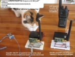
I've also tried narrow band tx (±15kHz) & slower baud rate ( 300bps) so the signals can be heard readily on a UHF scanner. This yields a pleasant purring sound when suitably SEROUT fed from a 08M -refer code on attached pix. A spurious sig. may well have been at work with my first range testing, as this time a good 200m thru' light timber frame suburban houses was achieved when on a scanner walkabout.
As well as a simple config. programmer setup (as shown breadboarded in pix), a decent UHF scanner looks a near essential when setting up these units. Better still would be a spectrum analyzer, as in urban areas the 434 ISM band is SO stuffed full of weird signals (security, doorbells,garage door openers,weather stations etc) that much time can be wasted locating YOURS. I've access to a prof. SA & will verify output purity, but just taming tx at moment- & awaiting HopeRF reply. Rx workout to follow. Stan
Attachments
-
 87.3 KB Views: 66
Last edited:
Stocky - good question! After much twiddling, in the end I set everything back to the widest "default" settings, (at 434 MHz), reasoning this would allow off beam tx signals to be still within the wide rx passband. It worked! The only change then made was to set a dead slow 300bps bit rate, simply to allow the distinctive "purring" signals to be readily found while on walkabout with my UHF scanner. Strange looks were in order as I paced off ranges with seemingly a purring cat in my jacket pocket!
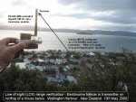
The receiver was easy enough to setup,although the delay as the 32 byte buffer fills is rather disconcerting in a WYSIWYG age. Sensitivity is perhaps not as good as expected, with comms ceasing when ~1 bar "squelchable" signals were still readily heard on the scanner. Sustainable comms ranges confirmed ~100m-200m thru' light buildings & vegetation, with ~500m LOS maximum range( ref. pix) From this same lookout spot I've trialled all manner of UHF & WiFi gear, with cross harbour ranges (~10-12km) a breeze with 500mW UHF CBs, & had easy "wokfi" WiFi links to the island 5km off shore. The ~½km LOS range of the HM-TR is really no better than numerous ASK 434 MHz offerings, & given the much lower power (a few mW? - 25mW is allowed in most countries) the HM-TR benefits look increasingly more like -
1. One stop- both tx & rx in the same package so more versatility & occupying less circuit space.
2. Possibility of ½ duplex error detection/correction.
3. Configurable, although somewhat involved if wanting non standard settings.
4. Being FSK ( Freq. Shift Keying) there's useful noise immunity compared with classic ASK (Amplitude SK) "on/off" keying
I'm parking things until I hear more back from HopeRF relating to queries I've raised. Stan
------------------------------------------------------------------------------------
As you were: Even as we speak HopeRF's ever responsive James in Shenzhen (mega factory city right over border from HK) emails to say -
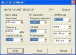
1. PA tweak shown at the config/setup screen is actually an attenuation measure, so 0dBm really means not attenuated. The terminology is thus shown incorrectly.
2. Raw output power has been reduced to 4-5 dBm "to meet ETSI regulations". (ETSI= European Telecommunications Standards Institute).
3. Only real difference between the freq. band offerings is that different "antenna matching' has been fitted. It's quite possible to set the 434 unit on the other bands -either 315, 433, 868, 915 MHz! The 434 unit itself can output anywhere between 430.24 MHz -439.75MHz (which of course ranges well outside the legal 433.920 MHz ISM band slot).
4. At least 4½-5½V supply OK (as I'd already confirmed)
5. On board SMD LED patterns relate to rx/tx, startup or setup activity (as I'd nutted out)
6. Cap freq. tweaking only really a narrow band issue, & not picky if wide band rx/tx used (as ditto...)
The receiver was easy enough to setup,although the delay as the 32 byte buffer fills is rather disconcerting in a WYSIWYG age. Sensitivity is perhaps not as good as expected, with comms ceasing when ~1 bar "squelchable" signals were still readily heard on the scanner. Sustainable comms ranges confirmed ~100m-200m thru' light buildings & vegetation, with ~500m LOS maximum range( ref. pix) From this same lookout spot I've trialled all manner of UHF & WiFi gear, with cross harbour ranges (~10-12km) a breeze with 500mW UHF CBs, & had easy "wokfi" WiFi links to the island 5km off shore. The ~½km LOS range of the HM-TR is really no better than numerous ASK 434 MHz offerings, & given the much lower power (a few mW? - 25mW is allowed in most countries) the HM-TR benefits look increasingly more like -
1. One stop- both tx & rx in the same package so more versatility & occupying less circuit space.
2. Possibility of ½ duplex error detection/correction.
3. Configurable, although somewhat involved if wanting non standard settings.
4. Being FSK ( Freq. Shift Keying) there's useful noise immunity compared with classic ASK (Amplitude SK) "on/off" keying
I'm parking things until I hear more back from HopeRF relating to queries I've raised. Stan
------------------------------------------------------------------------------------
As you were: Even as we speak HopeRF's ever responsive James in Shenzhen (mega factory city right over border from HK) emails to say -
1. PA tweak shown at the config/setup screen is actually an attenuation measure, so 0dBm really means not attenuated. The terminology is thus shown incorrectly.
2. Raw output power has been reduced to 4-5 dBm "to meet ETSI regulations". (ETSI= European Telecommunications Standards Institute).
3. Only real difference between the freq. band offerings is that different "antenna matching' has been fitted. It's quite possible to set the 434 unit on the other bands -either 315, 433, 868, 915 MHz! The 434 unit itself can output anywhere between 430.24 MHz -439.75MHz (which of course ranges well outside the legal 433.920 MHz ISM band slot).
4. At least 4½-5½V supply OK (as I'd already confirmed)
5. On board SMD LED patterns relate to rx/tx, startup or setup activity (as I'd nutted out)
6. Cap freq. tweaking only really a narrow band issue, & not picky if wide band rx/tx used (as ditto...)
Attachments
-
 128.5 KB Views: 79
 -
 81.2 KB Views: 56
Last edited:
manuka, got the antenas from HopeRF to?
teaking these rf modules with a simple low power 08M is awesome! Can u test ur mobo power consuption/autonomy with the 3 AA pack?
i'm "cooking" a remote 08M based RF perimeter alarm.
I,ve got:
- 2 solarcells (2,0V 100mA each);
- 4 supercapacitors (10F 2,5V each);
- 1 MAX856 dc/dc converter;
- 1 MAX982 open drain/dual comparator;
- 2 AAA NiCad batteries (1,2V 800mA each );
Ordering the 2 HF-TR 232 modules with antenas + passive components 4 the solar battery maybe this week. Need a 22uH inductor 4 the solar battery circuit but i have no idea what/wich tipe to order.
link's to circuit -> http://mcs.uwsuper.edu/sb/Projects/PIC/Solar/
counting on everybody to help me to cook this project on a further thread.
just a brainstorm 4 the skilled ones where. Remember the Kranenborg 2 line serial comunication protocol? it would be possible with this neat rf transceiver to develop a simple yet powerfull RF network of slaves/master units?
Whoops ! Sorry re current drain, which in fact is somewhat higher than anticipated- especially for the receiver. With a 3 x AA (~4½V) supply I found the tx takes 25-35 mA, while the rx pulsed 25mA to as high as 40mA. Naturally some of this relates to the 08M (~5mA ), with the extra breadboarded LED similar. Overall allow a working HM-TR to each draw ~25-40mA
Grounding the Pin 6 ENABLE puts them into µA level standby mode,& it's a doodle to SLEEP an 08M of course. System drain would depend on how frequently they were fired up, but I'd factor maybe a 5-10mA average each end.
Solar batteries. Making your own can be more involved than it's worth for low drain applications such as yours! For RF work circuit switching "noise" can be significant of course too. Why not just get a higher output PV? Thought- perhaps even rescue a few from solar garden lamps & string them in series? These typically give out 2V @ 30mA in bright sun each, so 3 would give enough to charge 4 x AA NiCds ( 4.8V), perhaps via a Si diode to limit supply voltage. In fact we've run a 08M, DS18B20 & simple ASK 433MHz tx directly from a single AA NiCd solar garden lamp, using SLEEP to lower overall current drain! The cheapie solar lamps flooding hardware stores here in NZ all have on board inductors ( 0.47mH) already - confusingly these look like a slightly fat resistor. "Talking Electronics" guru Colin Mitchell has A1 explanations of these => www.talkingelectronics.com/te_interactive_index.html
Stan
Last edited:
A good chip,but possibly an overkill for PICAXE work IMHO. Keep in mind 08M wide supply ranges (~2.7V-5.5V) for starters. "RF noise" filtering (which can confuse the PICAXE brain as well as blotting the spectrum) normally uses small caps (~100nF) at critical points- not large ones across the supply! Comapred with AM ASK, FM FSK of course is somewhat immune to impulse noise, but the PICAXE may still be upset. Read Colin Mitchell's account referenced above & do some test bed trials FIRST!
Last edited:
MAX756
yamato96
If I were to do this again I would go for a single 1.2V cell NiMH to avoid reverse charging of cells/cell in multiple battery pack designs when batteries become discharged.
http://groups.msn.com/picaxe/allweatherampprojectbox.msnw?action=ShowPhoto&PhotoID=113
yamato96
If I were to do this again I would go for a single 1.2V cell NiMH to avoid reverse charging of cells/cell in multiple battery pack designs when batteries become discharged.
http://groups.msn.com/picaxe/allweatherampprojectbox.msnw?action=ShowPhoto&PhotoID=113
Yamato96- maybe start a new thread on this as there is a lot to discuss on stepup converters. These are great chips and definitely work fine with single battery solar/radio but you need to get the right package. Texas Instruments have a fantastic range but the chips are not much bigger than a grain of sand - fine for pick-n-place machines but not so good for fat handed twats like myself! I think the 856 comes as a surface mount which are not too bad to solder.
Stan - comments about current drain are very relevant and much appreciated. With the standby mode does the module wake itself up out of that mode when it gets some RF?
Stan - comments about current drain are very relevant and much appreciated. With the standby mode does the module wake itself up out of that mode when it gets some RF?