Self-controlled power

testerrrs

New Member
Evening all,

Whilst playing around with some bits for my altimeter project, I decided it would be a good idea if the PICAXE, once finished logging, could power itself and the rest of the circuitry down completely, or as completely as possible.

After coming up with the following two ideas for doing this, neither of them work. Does anyone have any other ideas as to how I could get this to work?

Circuit 1:

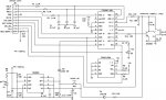
- The PTM is pressed and the transistor allows power down through the regulator to power up the PICAXE. The PICAXE immediately sends pin6 HIGH to hold the transistor base high, thereby keeping the circuit latched. To power down, the PICAXE sends pin6 LOW.
- Problem: It doesn't latch.

Circuit 2:

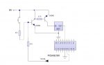
- The PTM is pressed and the thyristor latches. Power is allowed through the reg and the PICAXE powers up. When the program is complete, the PICAXE sends pin6 HIGH to unlatch the thyristor and power down the system.
- Problem: It doesn't unlatch.

Bearing in mind this must be a low power & low weight solution, a relay is unfortunately not a viable option.

Any thoughts on this appreciated!

Jon
 

moxhamj

New Member
One solution might be to run the picaxe all the time and then run any peripheral circuits off a picaxe pin. Picaxes can supply up to 20ma and, for example, op amps only need 3mA and digital chips are even less. So the picaxe turns off peripheral things, and then puts itself in low power mode which draws less than the self discharge rate of batteries. Use a low quiescent 5V regulator (lots of brands).
 

MFB

Senior Member
Shut-down regulator

Why not use one of the many regulators that has a dedicated shut-down input?

The MAX 883 for example (available in 8-pin DIL package). Initially closing a push-button can connect the ‘OFF’ (pin 7) to the input (pin 5) in order to apply power to the PICAXE. The first line of your code must then pull the ‘OFF’ input high, to hold the regulator on when the button is released. The last line of your code should take the ‘OFF’ pin low again to remove power from the PICAXE and associated circuitry. You will need to include a diode in series between the PICAXE output and the ‘OFF input (cathode towards to regulator). When off, the regulator leakage current is only in the order of nA.

The component count using a shut-down regulator is lower than the transistor/regulator approach. See the August issue of Nuts & Volts article, about a Flight Recorder, for an example of just such a (3V) PICAXE supply.
 

MartinM57

Moderator
Aaaarrrghhhh!

Another reference to the Nuts & Volts Flight Recorder that most mere mortals and skinflints don't gave access to ;)
 

sghioto

Senior Member
geforce,

Made a small modification to your origional schematic. This will work with the values shown. Of course you can substitute xistors and resistor values as needed.

Steve G
 

Attachments

D n T

Senior Member
Circuit 1 edit...

The problem you wrote was that the transistor was not latching.
Could you put a transistor in the 0 volt side that requires voltage to allow current to flow ( NPN transistor).
Then on the Base of that transistor would be controlled by a PICAXE ouput, your Press To Make switch, and a resistor capacitor network.
What I think this would do is allow the Picaxe to switch the output to LOW but still have power to do it .
Of course you may not need the RC network, you might get by, I haven't tried it yet
 

D n T

Senior Member
Turn off

Perhaps you might need to put your transistor on the 0 volts side, use an NPN and a resistor capacitor network to give the PICAXE " time to turn off".

Because I can't export a diagram , I will try to explain.

the output of the PICAXE charges the capacitor,
The capacitor + ve, the PTM switch and the picaxe output supply a resistor which supplies the base of the NPN transistor.
The capacitor -ve is earthed.


You may not need the capacitor in line but I thought it might help to "give the PICAXE time to turn off" and perhaps stop "oops"
When you press the PTM switch NPN completes the circuit, PICAXE is ON and charges the capacitor.
Let go of PTM, PICAXE keeps itself on and keeps the capacitor charged.
When the PICAXE wants to turn off, the output goes low and time passes ( not long if you like) the capacitor discharges and the transistor rurns off the current flow, turning of the PICAXE
 

jglenn

Senior Member
I have a uP unit I turn on by using a N-fet in the ground lead! Source lead goes to ground, drain to where circuit ground normally is, gate is controlled by a flipflop which has power all the time.

Martin: What do you want to know about the Nuts and Volts altm? There have been 2, actually, one used the picaxe, the other just a pic chip. Both have 3 axis accelermeters. The picaxe unit stored data in an FRAM. The data was read out with Excel using a plugin called SelmaDaq.

It really is sort of useless as a rocket altm. The designer does not understand rockets. It should read out in feet instead of G's! And rocketeers need 2 outputs, one at apogee and one for the main chute (maybe 500' above the ground). Nuts and Volts has a lot of good articles, and a few clunkers. But that was the first picaxe article that caught my eye, a few more and I felt I had to check the thing out. It's strongest point is the low cost compared to the stamp, and good programming environment.
 

gengis

New Member
A Self-biased (bias and supply from the same source) NPN transistor in the positive leg will drop about four volts - the way you show it. If you switched the base from a source of + voltage about four volts higher than the 9 volt supply it would only drop .6 volts.

Use a PNP transistor (emitter to + and turn on to ground) and you'll drop about 6 tenths of a volt and the circuit may work.
 

testerrrs

New Member
Thanks for all the suggestions guys, I'm working my way through them. A couple of problems I have experienced so far:

1) The system is running off 9V, and the regulator requires 7V minimum to output the regulated 5V supply. Using certain combinations of thyristor/xsistor mean the eventual voltage into the reg is <7V, which means it cannot work.

2) Running things from PICAXE output pins is a good idea, but does not work. The sensor requires exactly 5V, and the PICAXE output pins cannot supply exactly Vsupply. On my 5V regulated supply, the output pins cannot even manage 4V.

Will post back soon after I've done some testing and see what happens.

Thanks again,
Jon
 

MFB

Senior Member
Basic physics

I am surprised that you do not understand that accelerometers cannot be used to determine altitude. Its just basic physics really. Vertical acceleration can be integrated to yield a velocity profile and, by a second integration, peak altitude. This processing task is no great shakes once the data is in Excel. I think this was explained in Part 2 of the N&V article. The model rocketry book by Gavin Harper also describes this technique (but he uses a Basic Stamp based Flight Recorder).

Of course there are instrumentation errors associated with the above approach but then, as I am sure you will find out, there are also problems using pressure sensors (venting and air turbulence around the airframe etc). However, the main problem is that you are operating a 15psi sensor around only a small part of its dynamic range, with inherent errors due to temperature and barometric changes. Maybe that is why many commercial rocket altimeters use accelerometers.
 

jglenn

Senior Member
GE, you need a better reg, low drop out type, try a LM340AT-5
or LP2950cz-5.0, there are many others. With 5.5V in you can get
5V. Remember to have at least one 0.1UF close to the chip, a 1-10uF
electrolytic on the reg output is a good idea.

The baro rocket altm is the cleanest, because one sensor can
read peak and the second chute opening at about 500'. Accel units can only do the peak. We have learned to put the flush vent hole at least 5 body
diameters back from the nose cone joint, the airflow has stabilized at this point.
A small flush vent hole will read ambient pressure to mach speeds. But
the shock wave turbulence with crummy installations can blow the chute when going 900mph, so various methods have been developed to prevent that, a problem with baro altm.

I've worked with the gwiz, blacksky, rdas, missileworks, adept, and other units.

What is always fun is when they hit the ground at mach 1. Software or other problems can happen. Like forgetting to turn the altm on!

:p:p
 

moxhamj

New Member
Re :"2) Running things from PICAXE output pins is a good idea, but does not work. The sensor requires exactly 5V, and the PICAXE output pins cannot supply exactly Vsupply. On my 5V regulated supply, the output pins cannot even manage 4V."

That doesn't sound right. All the picaxes I have used output 5V on a pin when it is high (or maybe 4.99V sometimes but then the power supply reads 4.99 as well). It kind of suggests the power supply is collapsing.

Re voltage drops - transistors and thrysistors may have voltage losses but relays and fets won't. Maybe could you describe the application a bit more and we can come up with other ideas. For instance, would it matter about the power lost in a relay coil to keep it on? There are options using latching relays that could be worth exploring.

MFB - can you explain a bit more how to determine the apogee using accelerometers? I think it would be hard. If one sat inside a cannon ball and were fired out of a gun, there would be lots of Gs at launch then 0Gs through the entire flight if air resistance is negligable. If air resistance is signifcant then the calcs get complicated. If it is a rocket, there will be lots of Gs as the rocket takes off then 0Gs when the fuel runs out. But the apogee will happen later. And indeed, one might not even want a parachute to open at apogee anyway - maybe a bit later so there is not so much wind drift.

Re a 15psi sensor, 14PSI is 1 atmosphere so that would be a great sensor for going to outer space (100,000 feet = 99% of the atmosphere is below). There are lots of sensors with all sorts of ranges - just choose one that has the right range for the expected altitude. 1psi?
 

MFB

Senior Member
A 1 psi would be good if you were descending from high altitude but would be overloaded if you were launching from nearer sea level (nominally 14.69 psi or 68.947mbars). The N&V article was about ‘model’ rockets, that don’t tend to reach over a kilometre and therefore don’t need to use a delayed opening chute. For an idea of how little change in pressure the sensor will see in this application, take a look at www.gre.nasa.gov/WWW/K-12/airplane/atmosi.html. Even normal changes in barometric pressure would be significant over the expected altitude range of a ‘model’ rocket.

Regarding an explanation of using an accelerometer to measure altitude, I could not do better than refer you to the following paper by Larry Lynch-Fresher who designs commercial flight recorders. http://www.qwiz-partners.com.

I think we have hijacked the original topic (I only used the N&V article as a good example of a simple auto-shutdown circuit) and think we should start a new one, if people are really interested in general rocketry instrumentation.
 

jglenn

Senior Member
Gwiz made good units, but are out of business!

Baro sensors work fine for rockets up to 50,000', although the cal is touchy
way upstairs. You get the best resolution down lower. I have a 12 bit prototype based on the ADUC 12 bit cpu from analog devices, can resolve 3' down low and 10' at 50K.

To understand how to use an accelerometer to measure height, you need a little physics. Actually it was first done in the 1950's or before with vacuum tubes, called an "integrating accelerometer", for missiles, to determine when to fire the second stage.

The first integration of accel is velocity, when that is integrated you get displacement, or altitude. Note that a straight up flight is desired or there is error. That is an advantage of baro sensors, as they don't experience that error.
 

moxhamj

New Member
MFB - what an interesting article. The link is http://www.gwiz-partners.com/html/tech.html (you had a q not a g in your link). On the home page is a graph of accelleration over a flight.

The bit that I don't understand is whether this would work in real life. Sure, before GPS a jumbo jet could take off and by measuring the accelleration on the gyros one could determine the velocity and the distance. But these were always the experiments that never worked in physics labs when I was at school/uni! The error margins were always the unknown. Further down that article Mr Lynch-Freshner goes into some more detailed analysis of errors at 8 bits and higher. Intuitively I would have thought 8 bits would not even come close and even 12 bits might be pushing things - especially as the launch phase of these rockets is so short. But maybe it does work out ok and the errors cancel. The big question is whether a picaxe could do calculus in real time to sufficient accuracy. I wonder if op amp integrators/differentiators would do better or worse?
 

MFB

Senior Member
New thread anyone?

You would only need to process acceleration data onboard if you wanted to control something in real-time. Because the N&V Flight Recorder article is amid at model (not high power) rocketry use it includes details on exporting data to Excel for post-flight analysis (Part 2 also introduces a reliable method of real-time apogee detection using a magnetic sensor). The PICAXE/FRAM based designed can samples all three accelerometer channels at over 100 Hz, which should be adequate for post processing. However, the later PIC based design only managed 10Hz, which is definitely too slow. There is a good article some ware on the web that compares altitude measurements derived from an accelerometer and pressure sensor on the same model rocket but I have lost the address.

You know, I really do think we need to start a new thread before dealing with any more rocketry stuff.
 
Top