power with 1 input

alexthefox

Senior Member
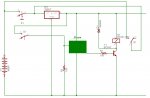
hi, i need to do a circuit (the software is ready) with this specification:

when a button is pressed, close two contact, 1 for the - or + power signal, and other as a input.

after 2 second 1 output of picaxe go high, and with transistor or relay close a contact to give the same power signal of the button, so when i relase the button the power is in the circuit.
again when press the button 2-3 sec, the out go low, and when relase the button the circuit dont have power. the program is ready, but i cant find the way to draw the power interface. ah, i forgot, i must to drive 12v.
thk
 

moxhamj

New Member
I'm a bit confused about this - could you post your code as this might help?

To turn on power (12V, 5V or any volts) the easiest solution is a relay. Page 7 of manual 3. Will the picaxe be always powered even when the circuit is off? If yes, you can save power with low quiescent regulators and sleep modes in the picaxe and get power consumption down so batteries will last years. But you might also want the power to really be off till the button is pushed. if so, push the button to connect power to the picaxe. Picaxe then turns on relay which also sends power to the picaxe. Button is released but power goes through relay to picaxe. Then when push button, picaxe turns off its own relay which switches itself off? Is this what you need. If so, I can draw up a diagram.
 

moxhamj

New Member
Ah, that makes sense on the schematic. Need to switch the high side rather than the low side. I will redraw in the next hour or so.
 

moxhamj

New Member
Attached schematic idea. Relay and switch in parallel. Push the button - turns on picaxe. Picaxe then turns on its relay. Release button - picaxe stays powered by the relay. Push button again - picaxe goes into powerdown mode - waits for button to be released and then turns off the relay and switches itself off.
 

Attachments

Last edited:

KMoffett

Senior Member
Since he said "transistor or relay contact", here's my entry:

Pushing SW2 powers the Picaxe.
Program: sets P0 high, turning on Q2 which turns on Q1, maintaining power to the Picaxe.
waits for P3 to go low, when the SW2 opens
sets an interrupt for a high on P3
program goes about its business
Pushing SW2 makes P3 high and triggers interrupt.
Interrupt sets P0 low, turning off Q2/Q1
program ends
When SW2 is lifted all power is gone.

Or the same with Dr_Acula's relay.


Ken
 

Attachments

Last edited:

moxhamj

New Member
Nice circuit. One advantage of KMoffet's mosfet circuit is it uses virtually no power when it is on. A relay consumes power to keep itself on which would be an issue with battery power.
 

alexthefox

Senior Member
Attached schematic idea. Relay and switch in parallel. Push the button - turns on picaxe. Picaxe then turns on its relay. Release button - picaxe stays powered by the relay. Push button again - picaxe goes into powerdown mode - waits for button to be released and then turns off the relay and switches itself off.


thank you Dr_Acula!!!!
last night i think exactly what you draw. with your help, and the help of all staff, everything is more clear, in find a different solution. THK to all forum peaples!!!
 

alexthefox

Senior Member
Since he said "transistor or relay contact", here's my entry:

Pushing SW2 powers the Picaxe.
Program: sets P0 high, turning on Q2 which turns on Q1, maintaining power to the Picaxe.
waits for P3 to go low, when the SW2 opens
sets an interrupt for a high on P3
program goes about its business
Pushing SW2 makes P3 high and triggers interrupt.
Interrupt sets P0 low, turning off Q2/Q1
program ends
When SW2 is lifted all power is gone.

Or the same with Dr_Acula's relay.


Ken
i try to do the circuit in 1st picture, but i dont understand what is S-G-D... and, can i change 2N7000 with BS170?
thk
 
Top