Wiss this circuit work?
- Thread starter RexLan
- Start date
BeanieBots
Moderator
Dunno, but doesn't need to be that complex.
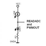
Simply arrange for your LDR potential divider output to be less than the LED V_forward and you can use ReadADC during the OFF period.
Simply arrange for your LDR potential divider output to be less than the LED V_forward and you can use ReadADC during the OFF period.
westaust55
Moderator
Wonder if something like this would work - or are you trying to drive a high brightness high power/current type LED ?
LDR, LED and R2 form a potential divider akin to BB's comment.
LDR resistance should be high enought to prevent LED illuminating visibly.
LDR variation with light level will give a varying value for READADC. Variation may be small.
When PICAXE drives pin high LED will operate as usual.
LDR, LED and R2 form a potential divider akin to BB's comment.
LDR resistance should be high enought to prevent LED illuminating visibly.
LDR variation with light level will give a varying value for READADC. Variation may be small.
When PICAXE drives pin high LED will operate as usual.
Attachments
-
 6.9 KB Views: 44
BeanieBots
Moderator
I really wish people wouldn't delete (or make major edits to) their posts AFTER people have taken the effort to reply
Well actually it was because we "drifted" off the question asked as you have elegantly pointed out in the past.Yes, very odd. Makes subsequent posts from people who have spent their time somewhat a waste of time and often meaningless.
Maybe it's embarrassment LOL.
(I must remember to use LOL a lot more if I'm just about to goof).
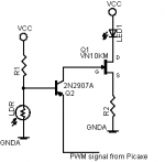
The circuit on the left ... never got an answer. All I originally wanted to know was if the Picaxe signal would pass through the PNP transistor.
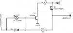
My embarrassing circuit on the right does in fact work.
Sorry ... I struggle with this stuff but eventually hammer out a less than elegant solution ... LOL.
Attachments
-
 1.3 KB Views: 16
 -
 1.9 KB Views: 15
Last edited:
westaust55
Moderator
No need to be embarrassed.Well actually it was because we "drifted" off the question asked as you have elegantly pointed out in the past.
The circuit on the left ... never got an answer. All I originally wanted to know was if the Picaxe signal would pass through the PNP transistor.
My embarrassing circuit on the right does in fact work.
The response may have drifted but in an endeavour to make the circuit easier/simpler and maybe misunderstanding the original question.
Sometime folks do go headlong into their pet solution instead of first answering the actual question - liek "will this work" . . .