Will this be sufficient to protect the Picaxe?

RexLan

Senior Member
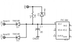
I have two input circuits. Both are sitting at +12v and I want to know when one of them goes to 0v (ground).

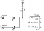
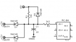
This is just the basic to show the question and the Picaxe is not finished, etc.

When either line goes to ground the input to the Picaxe should go low.

My question is with the 5V on the back of the diode and 12v on the other side do I still have adequate protection for the Picaxe or do I need to add something .... other than an opto.

Thanks for the help.
 

Attachments

Last edited:

boriz

Senior Member
The diodes will behave like low value capacitors when reverse biased. So a rapidly rising signal from 0v to 12v would leave 12v on the anode which would need to be discharged through the 10K resistor. From the pins point of view, every time A or B goes high, there would be a brief 12v ‘spike’. Worse if they both change together and they are changing fast.

The actual damage done can’t be accurately determined without detailed information about the signal rise time, the diode capacitance and the internal protection on the Picaxe pins, but it’s likely to be minimal.

So my answer is: It should be ok for prototyping, but probably not for the long term.

Better to use a divider.
 

BeanieBots

Moderator
Boriz has raised some valid points.
If those 12v signals are nice clean 12v signals, then your circuit should be fine.
If however, they come from some really nasty like a car 12v system, then you will need much more by way of protection.
 

techElder

Well-known member
I would add a reverse biased diode across the 10K resistor (cathode to +5v.)

This will dump any high-voltage spikes into the +5v capacitors should there be any spikes. If you don't have capacitors, get some.

(Did field repairs on engineering problems like this for many years ... mostly on table tops in industrial settings.)
 

boriz

Senior Member
Yeh. What he said.

Also wouldn't hurt to put a (say) 10nF cap between Picaxe pin and ground.
 

BeanieBots

Moderator
I would add a reverse biased diode across the 10K resistor (cathode to +5v.)
I wouldn't bother. It won't do anything. Any 'spikes' that get past the diodes will be too fast to be caught by a diode. I'd be tempted to add the 10nF suggested by Boriz though.

Without knowing the exact nature of the 12v signal, anything else can only be speculation.
 

MFB

Senior Member
A single channel opto-isolator chip might do the job and cost not much more than a zener circuit.
 

Dippy

Moderator
How about just adding a suitable resistor in series with each diode and let the PIC's clamp diode do it's job?
If worried add a schottky/fast clamp to +5 rail. i.e. an extra paralleled clamp diode.
 

techElder

Well-known member
Ok, but don't tell me I didn't tell you ... :rolleyes: :)

I wouldn't bother. It won't do anything. Any 'spikes' that get past the diodes will be too fast to be caught by a diode. I'd be tempted to add the 10nF suggested by Boriz though.

Without knowing the exact nature of the 12v signal, anything else can only be speculation.
 

Dippy

Moderator
I didn't read TCH's previous post properly.
He is suggesting the diode clamp method too.
I totally agree, however, I do think the extra little resistor I suggested will give a little extra protection.

Clamping that spike to V+ with a fast diode will certainly provide the protection you need as long as the pulse ooomph isn't too great (hence resistor).
It is a solution that costs less than 8 pennies too as a bonus.
I confess it is only once in a blue moon that I ever disagree with BB, sorry.
 

RexLan

Senior Member
I think I got it ... how does this look now?

The signal is a simple switch with both legs sitting at 12V. When activated one side will go low with some contact bounce but otherwise crisp. However the other side will remain steady at the 12V.

Thanks
 

Attachments

Dippy

Moderator
If it were me I'd inlcude (as I said before) resistor in series with the diodes going to your 'Inputs'.
This will reduce the amplitude of any pulse (and there WILL be a pulse as mentionedby boriz and BB).

You would also be advised to have an electro cap //ed with a ceramic cap decoupling your PICAXE supply. Any pulse will be diverted by the clamp diode onto the V+ line.
Does that make sense? It has been mentioned before but you don't appear to have acknowledged it so I don't know if you have understood the points made??
 

RexLan

Senior Member
If it were me I'd inlcude (as I said before) resistor in series with the diodes going to your 'Inputs'.
This will reduce the amplitude of any pulse (and there WILL be a pulse as mentionedby boriz and BB).

You would also be advised to have an electro cap //ed with a ceramic cap decoupling your PICAXE supply. Any pulse will be diverted by the clamp diode onto the V+ line.
Does that make sense? It has been mentioned before but you don't appear to have acknowledged it so I don't know if you have understood the points made??
Thanks Dippy ... Yes all makes sense. I will add two R's in series with the input lines.
Cost is no factor but physical space is a big concern ... may have to use SMD as it grows. I only have 1.5" x 2" enclosure available.

Size for series R ... 10K OK?

I will have proper decoupling, etc on the Picaxe. Just trying to show only the circuit of concern as mentioned in the first post for clarity
Thanks again
 

Dippy

Moderator
10K? Why?
Think about it, don't guess.
What voltage does PICAXE require at the input pin to see 'Low'.
(Often 0.2 x Vsupply, but isn't GP1 a TTL? so 0.8V max)
You have a 10K pullup plus Diode Vf, so you can do the maths.
Obv. you can change pullup and series res to suit.

Note: Ignore the fixed idea of a diode's Vf (drop) = 0.7V.
It varies with current and temperature. Check data sheets. At a microamp or so the Vf for a 1N4148 will be <0.3V.
And whilst it may be tempting to chuck in a schottky beware of Vr values in automtoive situation.

PS. Will I incur the wrath?
 
Last edited:

BeanieBots

Moderator
I confess it is only once in a blue moon that I ever disagree with BB, sorry.
Don't be sorry, good debate is healthy:)
(sending your strawberry back:p)

First off, IS this an automotive application?
If yes, then you need every bit of protection you can get.

If no, then what type of 'spike' is going to pass through a reversed diode that is big enough and long enough to be caught by a clamp diode?
What is the typical capacitance of a diode junction?
What is the typical capacitance of a PICAXE input?
What is the clamping characteristic of the internal clamp diode?

Add 10nF to the PICAXE input and how much reverse diode capacitance charge is left (after dumping into the 10nF) to bring the input above Vcc?

Simply disputing it's worth unless it's ultra, ultra fast and even then I'd expect it's capacitance to have a larger effect over any clamping action and that would be swamped by fitting a cap.

I go along with fitting a series resistor but between PICAXE and pullup so that it's value is (within reason) not important. (1k ~ 10k).
 

Dippy

Moderator
Well, I got tired of debate and 'scoped it.

I used a 25V instead of 12V.
And a 47nF X7R decouple cap.
My input diode was a 1N4001, so a bit fatter than your spec.

Results.
The internal clamp almost got rid of spike. But not really good enough , I wouldn't be happy.(rise time of a few dozen nanoseconds)
A paralleled 1N4448 made not much difference, but made me happier.
A parallel BAT85 completely got rid of it. Lovely chubbly.
A 4n7 X7R cap made me feel even happier though you might need a larger value for healthy debounce effect.

The spike introduced onto 5V line without a ceramic decouple was significant.

So, now I risked my PICs you can get on with it ;)
Moral. Spend £1000 on a 'scope and then you can do it yourself :)
 

BeanieBots

Moderator
Thanks Dippy, very considerate of you to do a REAL test.
Fully support your moral:D
Shame you didn't try cap with no diode.

(In a dilema what to do with that stawberry now:confused:)
 

RexLan

Senior Member
OK you guys ... no, this is not an automotive application. I have subsequently restricted myself from that field after the last thrashing I received and will now concentrate my efforts exclusively on commercial airline applications!

Actually, I am making a little solar panel transfer thingy for my motorhome but it runs on the coach battery system. If one shuts off it will cause the Picaxe to tell me about it. Low tech, but that is all I can do anyway.

Dippy I asked about 10K because I have several thousand of them left over from the old days .... LOL. Aren't most designs arrived at from the "junk box"? I have some 2K2's laying around though.

Thanks again
 

Dippy

Moderator
"Shame you didn't try cap with no diode."
- I did, but didn't record the results. I think it was beneficial.

Oh, THAT strawberry. It would be popular in some of the Brighton clubs.

Rex, I'm reluctant to say specific values, follow BBs suggestion. Your 2K2 may be alright. I'd use 1k0 as DrAc says that is universal ;)
 

John West

Senior Member
Are those 12V inputs actually being pulled to ground? If so - how? Just curious. I Ask this because it appears you are monitoring which batteries are in circuit but don't mention anything about the nature of the disconnect. Disconnecting from 12V is not the same thing as pulling to ground.

Admittedly my scanning of the thread was quick. Did I miss something?
 

RexLan

Senior Member
Good point ... Yes ... they are actually sinking the line ... not just removing the voltage. I checked that with a simple LED already to see if it held it off.
 

John West

Senior Member
Good point ... Yes ... they are actually sinking the line ... not just removing the voltage. I checked that with a simple LED already to see if it held it off.
That was indeed what I was wondering about. Your diodes already bring you up above zero volts - and once you start adding pull-ups and input current limiting resistors you wind up with a voltage divider voltage based on the impedance of your "low" level to ground - ones that can leave the signal voltage at a questionable level for reading as a "low." As long is it's just a few ohms or less - or if an active device it can sink substantial current - you're fine.

Have fun. I'm working on my own PICAXE control and monitoring system for my motor-home. I live in it full-time so a good system adds a lot to both my comfort and the rig's functionality. I have half a KW of PV panels to hook in and I'm looking forward to doing an expandable PV control and monitoring system and integrating it into the rest. So I read closely anything on the site pertaining to motor vehicles or "caravans." Lots to learn in that regard. Mostly about spike and noise suppression and circuit protection.
 
Last edited:

RobertN

Member
Be aware vehicles can have transients of + and &#8211; 60V. That and the max I/O clipping diode current sets the signal input series resistor value times 2. These are proven input circuits used for heavy vehicle applications for over a decade, and have passed numerous EMI and electrical tests.

The digital (switch) and analog input circuit, starting at the input connector.

A .01uf cap to chassis for suppressing EMI,
10K pull-up to 5V and 100k pull-down to ground,
3.3K series resistor, Limits current into clipping diodes and forms low pass filter with .1uf cap below.
.1uf cap to ground, another 100K to ground,
2 clipping diodes, one cathode to 5V, and the other anode to ground

Analog inputs are the same except no 10K pull-up.
A separate 5V clamp source is sometimes used to prevent clipped noise and currents from disrupting the 5V supply
 
Last edited:

boriz

Senior Member
This.

When the signal (A or B) is high, there will be 5v on the cap, then when you close the switch, that 5v will need to be discharged through the switch and the diode. It’s a small cap, so not many watts, but the peak current could briefly be large (depending on the cap ESR). Slight damage to the diode and capacitor might accumulate.
 
Top