weather sensor problem

pleiser

Senior Member
Hi, I am making a temperature sensor transmitter using axe213 transmitter and ds18b20 temperature sensor (my first project of my own design) and when I turn it on the picaxe faild to program(hardware not detected) then I noticed that the picaxe (and battery) was getting frighteningly hot (did not burn me but got close.) when I tested with a multimeter I got aceptable voltage (3.08 volts) across picaxe +volts and ground pin.
I am powering it with a circut from ron hackett's PICAXE evil genious book
(premade version avalible here http://www.jrhackett.net/BBP-01_Docs.shtml .)does anyone have any ideas?
(I will post pictures soon)
 

premelec

Senior Member
It's indicative of a wiring error or solder bridge somewhere - since you got a reading on PICAXE voltage it's possible an output pin is shorted - please do post your pictures and indicte power supply and chip in use... hope it's not damaged... !

To start tracing remove the PICAXE and see if you still draw too much current - if so then it's probably your power wiring...
 
Last edited:

SAborn

Senior Member
I done a similar thing a while back only to find some fool here (me) had connected the DS18B20 around the wrong way, they dont like it and fail to work afterwards.

I read the data sheet, looked at the pinouts, held the component in my hand to match the pin order, then flipped it over before installing it, then wondered why these sensors make better heaters than temp sensors.

As im sure you would not have been silly enough to make the same stupid mistake as i had, but you might want to check the sensor is in the right way around, incase you to have had a Murphy Moment.
 

pleiser

Senior Member
overheating fixed, cicuit not

Hi,
I found and fixed the overheating problem (a cut stripboard trace re filled with solder(pumping 9 volts into the poor picaxe:())
but the check firmware version results in hardware not found,I tried a new microcontroller with the same result.
any ideas?
Patrick
 

premelec

Senior Member
The picture in post 4 has shorts everywhere as traces don't seem cut... :) It would be very helpful to have a good picture of top and bottom of your actual unit... I do better with perf board with no strips and then add wires as I need them... but everyone does as they feel capable with... I have had trouble in the past with strip board with areas not cut out right etc... I use a Dremel tool to buzz into the substrate so no copper whiskers remain :)
 
Last edited:

SAborn

Senior Member
I use a Dremel tool to buzz into the substrate so no copper whiskers remain :)
A sharp drill bit (about 1/8 or 3/16) works a treat, nice clean cuts by just a few twists in the finger tips, no need for a dremel.
The drill bit makes it easy to see where the cuts are too.
I have used a dremel too but its a mess compared to a sharp drill bit.
 

Brian M

Member
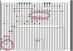
Is it me being stupid or am I correct in saying that on the stripboard diagram posted, the opposing pins are shorted out. You need to sort out the stripboard first. The sensor also seems to be floating (not connected to anything other than stripboard tracks going nowhere).
 

SAborn

Senior Member
Golly Gee! i just had a look at your drawing and think you best find a sharp drill bit.
I dont think the chip would be dead as the 5v and 0V pins are a dead short.

You need to review the circuit layout with more care, or find a better diagram as i seem to remember someone else having trouble with this author and his diagrams only a few weeks back.

For starters the tracks under the picaxe chip all need cuts in them as its a pin to pin short as they are at present.

The programming socket might need so cuts too if the socket has more than 3 pins (as most do) or you will have shorts there as well, as for the rest of the circuit .......??? i gave up looking once i had seen these mistakes and can only imagine the rest might be a mine field also.

weather station.JPG
 

westaust55

Moderator
You need to review the circuit layout with more care, or find a better diagram as i seem to remember someone else having trouble with this author and his diagrams only a few weeks back.
@SABorn
You may wish to be careful about inferences. From post 1:

Only the power supply was from/designed by Ron Hackett:
I am powering it with a circut from ron hackett's PICAXE evil genious book
(premade version avalible here http://www.jrhackett.net/BBP-01_Docs.shtml .)
The OP has designed his own strip board for the PICAXE
I am making a temperature sensor transmitter using axe213 transmitter and ds18b20 temperature sensor (my first project of my own design)

However, I concur with the use of a 1/8th inch drill twisted between the fingers as a means of cutting strip board tracks. Have used that technique for several decades without a problem.
 

hippy

Ex-Staff (retired)
However, I concur with the use of a 1/8th inch drill twisted between the fingers as a means of cutting strip board tracks. Have used that technique for several decades without a problem.
I'm going to dissent here. Having 'done it on the cheap' for years using a drill bit I always found I was cutting into my fingers doing a lot of holes. You can't beat a real stripboard cutter IMO, easier and quicker, and reliable results ...

http://www.techsupplies.co.uk/PCB005

And the price is a bargain, about a third of what I paid in a well known high-street component retailer.
 

srnet

Senior Member
I'm going to dissent here. Having 'done it on the cheap' for years using a drill bit I always found I was cutting into my fingers doing a lot of holes. You can't beat a real stripboard cutter IMO, easier and quicker, and reliable results ...
Second that, lot more control with a stripboard cutter.

Mine must be now be over 30 years old ......
 

Paix

Senior Member
I have to agree with Hippy on the cut fingers, but a bit of pencil and a blob of epoxy or superglue will make a good handle with a 3mm drill bit inserted.

A packet of ten 3mm jobber drills costing quite a bit less than the Official tool. A few turns of Gaffa tape for a quick job.

After all Hippy, it doesn't need to be bleeding edge technology :)

The money saved could be put to good use buying a magnifying glass and a LED torch (batteries not included) in the local ££/$$ store. Board checking is then up to Pleiser and a spot of due dilligence. Which can be purchased at the school of hard knocks for the price of a few toasted components.
 

hippy

Ex-Staff (retired)
A packet of ten 3mm jobber drills costing quite a bit less than the Official tool. A few turns of Gaffa tape for a quick job.
True, but we're not talking about an excessive cost and it should last almost forever.

Pain I can often live with but I also found drill bits didn't always make for a good cut anyway, needed multiple turns, were prone to leaving a small element of track or cut into the board too deeply; I guess official cutters have a better cutting edge angle.

It was repeatedly finding holes not cleanly cut, leaving tracks joined and hours of trying to tell where, which was the final motivation for buying the real thing. The time saved in having no rework to do has more than covered the cost.
 

pleiser

Senior Member
Golly Gee! i just had a look at your drawing and think you best find a sharp drill bit.
I dont think the chip would be dead as the 5v and 0V pins are a dead short.


For starters the tracks under the picaxe chip all need cuts in them as its a pin to pin short as they are at present.

The programming socket might need so cuts too if the socket has more than 3 pins (as most do) or you will have shorts there as well, as for the rest of the circuit .......??? i gave up looking once i had seen these mistakes and can only imagine the rest might be a mine field also.

View attachment 10575
I cut the strip board traces under the microcontroller but forgot to put it on the diagram and my programming adapter does have only 3 pins (seen here http://www.jrhackett.net/connectors.shtml it is the low profile stereo connector (3.5mm)
I am also using a drill bit turned by hand to cut stripboard traces (mine has a handle.)
saborn, yes I used his method of designing striboards (It is easy and works well.)
 

Attachments

Last edited:

premelec

Senior Member
I suggest - short of actual pictures of your hardware - you draw a large schematic diagram of what you want to build and then check off one wire and one part at a time being correct on your stripboard. When I say 'check off' I mean actually line by line on the schematic cross off that the wire IS properly in place. It doesn't matter how you cut the traces - only that conductors be connecting only the things they are supposed to... You need a one-to-one correspondence of schematic lines to hardware conductors and evidently some just aren't there - or your schematic is incorrect... good luck with it...
 

pleiser

Senior Member
problem fixed! :)

I found out that the problem was a missing wire for the ground on power the supply portion.
thanks everyone for the help. :) it succesfully programed with a program to use readinternaltemp (until the ds18b20 arrives).

Patrick
 

premelec

Senior Member
Now that wasn't so hard was it? :) glad you've got it going - persistence does the job... Don't forget the resistor in conjunction with the DS18B20...
 
Top