watchdog for 433MHz modules

nickwest

Member
Hello again, I asked a few questions about multiple SERINs on one pin at http://www.picaxeforum.co.uk/showthread.php?t=7139 For those who don't want to read that thread, I have an 08M listening to serial data via a 433MHz wireless module. The remote transmitter sends one byte every ten seconds or so. To prevent the 08M hanging I also have a second 08M acting as a watchdog, sending a dummy serial byte if it isn't reset by the first, master 08M, after about 60 seconds.

Now the above configuration works 100% reliably on the breadboard, with the remote module connected via a cable, ie. omitting the "wireless" part of the link... so two inputs from two PICaxes is fine, but one input from a PICaxe and one from a wireless module doesn't work. Either one works on its own (so I know the wireless connection is solid)

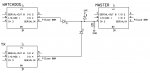
Both inputs are the same n300 data, with identical qualifiers etc (both of them work fine when hard-wired to the master PICaxe) Could there be an issue with the wireless module and the PICaxe giving different amplitude signals, or noise from the wireless RX drowning out the serial output of the watchdog? Have any of the wireless gurus had a similar problem? The serial sources are isolated from each other using the diode network suggested in the above thread, this aspect at least I did get to work!

Finally, has anyone tried isolating the watchdog's output with a transistor, and only "switching it in" when it is required, ie the watchdog is not connected to the master PICaxe except when it is sending its dummy serial byte.

I hope that makes sense to everyone, please let me know if I can clarify anything.
 

nickwest

Member
CORRECTION: if my theory that noise from the Rx is drowning out the watchdog's serial signal, I guess I should try to isolate this temporarily while the watchdog is sending its data... not isolating the watchdog the rest of the time.
 

moxhamj

New Member
That thread ended with a question about the polarity of the diodes. I am very confused about the actual schematic. Could you kindly post a drawing? I can think of all sorts of problems - I wrote them all out but have just deleted them as it is too much guessing and too many possibilities. There are solutions. I have a circuit listening to 3 RS232 lines and a radio Rx all at the same time. But just post your schematic for starters pls.
 

hippy

Ex-Staff (retired)
RF shouldn't be drowning out the 0V/5V serial line, at least not at the power levels likely being used here. I note you're using N300 baud; depending on your RF hardware it may be necessary to use T300.

To go to T300 will probably involve reversing the mixing diodes. It shouldn't be necessary to have to use a transistor.
 

nickwest

Member
Dr_Acula: Here's the schematic of the relevant parts. This setup works OK until the "TX" is replaced with a 433MHz RX. In this case the "MASTER" receives the wireless signal but doesn't respond to the "WATCHDOG".

With the wireless RX in place of the "TX" PICaxe, I tried isolating its data line with a transistor, to briefly disconnect this data line when the watchdog was transmitting. This works a treat, but as Hippy points out, shouldn't be necessary. Surely there is a more elegant solution?

Dr_Acula, maybe you could post the relevant parts of the circuit you mention?

Thanks again.
 

Attachments

Dippy

Moderator
Have you tried 'scoping the output of your RF Module?
(Eh? Don't tell me you're doing this kind of project without a 'scope??)
I haven't tried every module ever made but it may surprise you....
Noise maybe swamping your watchdog.

So, (possibley?) you may have to attenuate your RF during watchdog (e.g. ground the RF Data signal briefly), or switch it out of circuit or even briefly power-off the RF module.
But I really think most of this would be redundant if you used an RF Rx Module which has an RSSI output which you can sense.
I really don't know why people don't spend the extra pennies and get RSSI which is so easily ADCable.
 

nickwest

Member
I'm still trying to organise a CRO - these things don't grow on trees I'm afraid. An LED across the output of the RF module flickers like mad when the TX is off. As stated above, I now have a transistor switching this line out of circuit when the watchdog is sending serial data. It might not be elegant but it seems to work.

Perhaps my cheap RF module is just particularly noisy - is this a common issue?

I'm not sure if RSSI would help in my application - I have no control over the TX possibly wandering out of range... this is why I have a watchdog to warn me when I can no longer detect the TX.

Amazing how a seemingly simple project keeps growing in complexity...
 

hippy

Ex-Staff (retired)
Remove the watchdog, remove the blocking/mixing diodes, take the switching transistor out, and get direct RF to PICAXE working first. If simple won't work then complicated stands no chance.

There have been comments about Txxxx baud rates needed with some RF modules and your setup simply won't work if that's the case, you'll need a ( hopefully simple ) software and circuit re-design.
 

Dippy

Moderator
"I'm not sure if RSSI would help in my application - I have no control over the TX possibly wandering out of range"

- this is precisely where RSSI helps. By measuring the RSSI (via ADC for example) you can send your code into receive mode when a signal level threshold has been reached. A line or two more will give you an auto 'squelch' contol so you can ignore signal levels that you consider will give unreliable data. No need for watchdog for the RX.
 

nickwest

Member
Hippy: I've tested the RF serial input on its own and it works fine. I've learned the hard way to test every single stage of a project on its own... which is why I was so mystified when two parts that work fine in isolation won't play nice together.

I have been using inverted serial data because everyone else seems to when doing serial comms between PICaxes, is there another reason for this? Are there pros and cons to using inverted vs true serial?

Dippy: Regardless of the signal level, wouldn't the PICaxe still "hang" if a valid serial byte wasn't received?

For now I might just stick to switching-out the RF data when the watchdog is sending, at least until I can try a few different RF modules.
 

moxhamj

New Member
I'm still a bit confused by what works and what doesn't. The noise coming through the RF receiver is normal - at 433Mhz much of that noise is the background noise left over from the big bang. But a picaxe sitting in a serin state is looking for specific patterns in the noise. It doesn't matter if you use T or N, though some transmitters use less power if they have a low applied to them most of the time.

Can you post the code - specifically do you have some "U"s and do you have a qualifier like "ABC". And if you want to be really fancy, do you have a checksum?

With all these, you might be able to simplify the circuit and leave out a picaxe. If you have a picaxe listening to the radio and it is hanging in serin, and it gets a packet and the qualifier matches and the checksum matches, then you can be sure that is a valid packet. So that picaxe could raise a line high to say it has a valid packet, and then half a second later, send out the data to the second picaxe using the same line. The second picaxe can poll the line by testing if it is high, and only if it is high, go into a serin itself. Polling a line does not hang a picaxe. Then maybe you won't need that third picaxe.

Some modules don't like being too close to each other. Some need a big cap as they droop the power supply when transmitting.

If there is ever a chance of data clashes due to diode mixing, you certainly need data packets with headers and checksums.
 

hippy

Ex-Staff (retired)
Thinking about it, you will need some means of muting the RF receive line.

The diode mixing creates an active-high OR gate. For the watchdog to work what it sends has to be rceived correctly. If the RF is churning out random noise, that will interfere with what the watchdog sends and it's unlikely there ever will be a qualifier match. The test with a PICAXE instead of RF works because it isn't churning out noise when inactive.

You did say in your first post that you had RF working with the PICAXE so apologies for forgetting that. To redeem myself, here's a solution which should work without needing a transistor ...

Code:
.-------------.     ___                       .--------.
| RF receiver |----|___|----.----|>|----.---->| PICAXE |
`-------------'             |           |     `--------'
                            |           |
.-------------.             |           |
|             |-EN----------'           |
|   Watchdog  |                         |
|             |-TX---------------|>|----'
`-------------'
Make the EN pin an input when RF receive is allowed, make it an Output Low when it needs to be muted.
 

moxhamj

New Member
Hmm. I'm even more confused after reading Hippy's post, as I realise I might have been reading the original schematic all wrong. The original schematic doesn't show the actual radio modules so I guessed they were talking to a certain picaxe but I think hippy is guessing a different one. Any chance of a schematic showing the RF modules?

One potential problem is how to mask out hearing your own transmission if you are doing transmitting and receiving. You can do it in software. You can use the Hope modules. You can use a time delay.

Anyway, back to hippy's schematic, the RF receiver is going to be producing noise all the time so you can't diode mix any raw data coming from a receiver until it has been filtered. There are three filtering methods that I know work:

1) Dippy's method using a RSSI and squelch.
2) Use the Hope modules - these have their own onboard microprocessor so the only thing that comes out is clean data.
3) Use a picaxe 08 which has the sole function of sitting listening in a serin, and only outputs data that is valid. So RF module=>08=> diode mixing or whatever=> master picaxe.

Any of these will work. But diode mixing raw RF with any valid signal is going to result in neither signal getting through reliably.
 

hippy

Ex-Staff (retired)
This mechanism should work but does have problems I'll come back to.

If the RF is quiet then the PICAXE will hear nothing and SERIN will wait, if the RF is noisy the SERIN will read random characters but they won't match the SERIN qualifiers so SERIN remains waiting, if RF is up and running the signal should be noise free so SERIN will read the bytes, see the qualifiers, read the data and the code will continue.

The muting works to shut up the RF noise so the watchdog can send a clean message which will kick the SERIN out of waiting.

The problem, is that in this case the watchdog is sending every minute ( or whatever ) and it will trample over what the RF does really send at that time. This can have two manifestations; data from the RF is lost ( hopefully not every time ), or the RF may have sent the qualifiers just as the mute kicks in and the data byte ends up being replaced by the first byte te watchdog sends out which could be interpreted as correct data when it isn't and be acted on. Aslo it is possible that the random RF noise does match the qualifiers and wrong data can get through that way.

If that's what you meant by unreliable, we're both singing from the same hymn sheet.
 

hippy

Ex-Staff (retired)
Thinking about random noise, no matter how many qualifiers, how many check bytes, how strong a checksum, how many consecutive same messages have to be received to be considered valid, there is still a possibility that a random message could get through masquerading as a real one.

Statistically the more checking and verification one does the odds of that happening tend towards one in more than there are atoms in the universe, but equally, Sod's Law says it will happen more regularly than that.

Only RSSI or something which can distinguish between background noise and real transmission is reliable.
 

Zizka

New Member
Caution: rambling post.

Fascinating subject this: at what point does the likelyhood of a false decode become insignificant (it's never zero).

Using biphase coders, a 48 bit burst is (in my observations) "falses" vanishingly infrequently. A 24 bit burst I have seen false decode on noise, but I've only seen it once, while a 16 bit falses often enough to observe on the bench.

It's all really based on probability. In the simplest case it's a probability (per burst period) of 1 in 2^(decoded bits).

Look at the POCSAG pager code spec. The decoders I used to work on (too many years ago) false called about once every month on average, which was considered acceptable.

("Acceptable" is all down to what the application is. A false trigger event once per week would be fine on a camera pan/tilt. On a pyrotechnic initiator that would be catastrophic)


Adding RSSI based carrier detect greatly reduces the raw noise false decoding rate, but under interference conditions (especially impulse noise) it can still occur, and unless the threshold is set very high (deafening the receiver and reducing the range) a false decode can still occur on a data burst intended for a different receiver.
So even with a carrier detect, you still need enough decoded bits to discriminate wanted from noise, or corrupted bursts.
 

Dippy

Moderator
To anyone watching let me just say that Zizka has probably got more experience in radio modules than the rest of us put together so remember his wise words.

A question to Zizka relating to this thread:
Assuming that nasty RF interference is minimal and that the system has to be quite simple, what method would you suggest to get around the blocking effect of the Serin command on many PICAXEs (i.e. no timeout if no serial data)?
 

hippy

Ex-Staff (retired)
@ Zizka : I think you're right, there's no such thing as a perfect solution. If RSSI is fooled it can still give a false trigger.
 

moxhamj

New Member
Excellent question Dippy. The evil Serin Hang. It has consumed much time and effort on my part with workarounds and extra chips and the like. It has (almost) pushed me to resurrecting a Z80 board. Oh for a timeout on Serin...
 

Zizka

New Member
To attempt to answer the question posed:

(my experience on picaxe is minimal, so excuse my possible fumbling)

So the serin command waits for a valid byte, and while doing so, everything stops ?

Then I'd go with an idea already suggested here: use a secondary pic(axe) which just looks at the rx output and decodes it. When it gets a valid burst, it signals to the main processor (with an interrupt?) and then transfers the data (by serial, parallel, I2C or whatever).

The thing is, this also allows the use of data formats other than standard uart-type asynchronous, which has rather poor s/n performance compared to various biphase (Manchester, and it's cousins) codes. (I've not tried to write biphase coders in picaxe basic, as the code requires some fast processing, but it's very easy in assembler)

As an aside, biphase codes also give good dc balance, unlike rs232 type datastreams whose unequal high/low durations will upset the data recovery circuits of simple data radios.

[ There is another idea worth thinking about: don't use the serial port.
Connect a dedicated comms processor to a parallel port and handle the radio through it.
Or, If your datarates are low enough, you can use a DTMF coder/decoder pair and send your data 4 bits (1 of 16) at a time. Although very slow, DTMF decoders are extremely good at extracting weak signals from noise. Holtek make some good ones, currently ]

Good luck
 

Zizka

New Member
I found that parallel interface radio controller chip.
Called an RPC, you can find it at the end of the RPC2A module datasheet on the Radiometrix website. (Why it doesn't have it's own entry I don't know)
 

nickwest

Member
Yes, DTMF would be perfect, it's a shame the PICaxe can't do it natively. Right now the 433MHz modules are working beautifully over the length of the room, and when I turn off the TX the watchdog does its job. However if my RF modules can't handle a serial byte over a decent range I'll probably just accept the higher parts count and power consumption and go for DTMF. I only need to transmit three different states ("trinary" I guess?) so DTMF has more than enough "bandwidth"... not to mention that the states I am monitoring only need to be updated every 15s or so....
 
Top