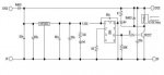
"So Dippy, do you agree I should put a big resistor where I currently had the 47n?"
- yes, as Martin says above in Post 37.
"And for the cap between the +V/0V pins, is the size and type important?"
- yes, that's why I suggested you read up on it. A good start would be searching on this Forum for decoupling...
Here is some more general information. Please read it as it'll save me 30 minutes of typing")
http://focus.ti.com/lit/an/sloa069/sloa069.pdf
(Save a copy, it really is a good reminder and written by someone with a sense of humour and a grasp of what goes on in the real world )
Markings?
A 47nF = u047 = 473.
Disc/Lumpy Ceramics are usually marked 473 = 47 x 10^3 picoFarads.
The whole point of decoupling is , like I said before, to 'divert' (or 'bypass') the noise away from the chip. In this case, we effectively, divert/bypass some of it down to ground.
How much is diverted depends on value, construction and type. Read up on dielectrics and capacitor type performance related to frequency. Read Manufacturer's Data Sheets.
100nF (104) should be fine for this circuit.
In some noisy/RF circuits people parallel a few caps together. Smaller caps will have a better HF performance (in addition to good dielectric choice).
Anyway, big subject. You'll learn a lot if you have a gentle read of good source material. I'm puffed out now.
- yes, as Martin says above in Post 37.
"And for the cap between the +V/0V pins, is the size and type important?"
- yes, that's why I suggested you read up on it. A good start would be searching on this Forum for decoupling...
Here is some more general information. Please read it as it'll save me 30 minutes of typing
http://focus.ti.com/lit/an/sloa069/sloa069.pdf
(Save a copy, it really is a good reminder and written by someone with a sense of humour and a grasp of what goes on in the real world
)Markings?
A 47nF = u047 = 473.
Disc/Lumpy Ceramics are usually marked 473 = 47 x 10^3 picoFarads.
The whole point of decoupling is , like I said before, to 'divert' (or 'bypass') the noise away from the chip. In this case, we effectively, divert/bypass some of it down to ground.
How much is diverted depends on value, construction and type. Read up on dielectrics and capacitor type performance related to frequency. Read Manufacturer's Data Sheets.
100nF (104) should be fine for this circuit.
In some noisy/RF circuits people parallel a few caps together. Smaller caps will have a better HF performance (in addition to good dielectric choice).
Anyway, big subject. You'll learn a lot if you have a gentle read of good source material. I'm puffed out now.