Very brief IR signal detection during program run.

colinsmurph

New Member
Hi, this is my 1st post so please try and put up with me if it sounds a littel stupid.

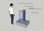
I need to sense ball beeing droped past a known point and trigger a light sequence, hold the end of the sequence for time X or untill another wooden ball is droped.
The system may also have a "sleep mode" where another light sequence may need interupting by reading the IR...

I have to use a IR distance sensor mounted at the top of a 250mm diameter perspex tube to sense a 30mm wooden ball falling past (i was considering using the Sharp GP2D120)

I am concerned that If i simply look for the IR voltage to be > X I may miss the event while the wait comands, and or light sequence's are active and IR is not currently beeing monitored.

I have ordered my 1st ever Picaxe, 28x1 and hope to use it for this project.

Thanks in advance for any help!!
 

MartinM57

Moderator
In principle, sounds easy enough

Instead of thinking about you having to read the IR signal periodically (and the problems you have noted already) think about the IR signal telling your program when it has changed, and your program then responding....to which the answer is interrupts

Have a look in Manual 2 about setint..and come back with any questions...

PS Welcome to the Forum :D
 

Dippy

Moderator
As Martin says; sounds easy.

However, SO much is missing from your description to provide a 100% answer.

As far as choosing a senor much depends on the required speed of response.
"I have to use a IR distance sensor mounted at the top of a 250mm diameter perspex tube to sense a 30mm wooden ball falling past"
250mm diameter perspex tube... falling past.
Falling past where?
That doesn't tell us how far the ball is likely to be from the sensor.

Can you draw it please and post it (Draw a JPeg and use "Manage Attachments" button below).

"falling past"
Just rolling past or dropped from 20 metres? How fast is this ball likely to be moving?
If we know the speed and distance from sensor you (we) can calculate the desired response time.
Give us a drawing and some likely speed figures and some likely distance (sensor-ball) figures.

Have you checked to see if the response time of that sensor is fast enough?
BTW, What is the response time of that sensor?

If the budget is no problem then just buy one and give it a go and forget all the above ;)
 

colinsmurph

New Member
Picture of arraingment

Thank you both for your speedy replys, :)

As requested here is a rough Jpeg of how it will be arrainged,
The user should drop the ball from the opening but i guess it may be from 50-100mm higher.

I think the "Interupt" is what i needed thanks for also giving me the
"correct way of looking at it"

I havent done any programing for the last 15 years so its coming back in drips and drabs.....

The sensor should give an output every 38m/s
between .4 volts at 300mm (no object)
and 1.2 volts 100mm (object present)

Will i have to specify the voltage in required for interupt? and if so how would i do this?

Thanks again
 

Attachments

Last edited:

Dippy

Moderator
A very pretty drawing :)

Mmm... this means the sensor may be outputting a value as it will probably be detecting the inside of the shiny perspex tube.
As to how it changes when a ball drops I really don't know.

Remember those low cost sensors just work on reflected intensity, so direct shiny IR may mess it up.
I'm not sure if angle is significant on those sensors.
So I haven't a clue as to change in signal level when your balls drop.

It may require a comparator style detection or fast ADC loop.
Or what you are doing may be perfect.. who knows.... apart from you.

I suspect that you are going to have to do some experimenting if you choose that sensor.
If money is no object then have a go.
Or could you just fit one of those much cheaper LED/IRph-tr sensors right under the ball hole?
Possible options: http://uk.farnell.com/jsp/search/browse.jsp?N=500006+1004259+5448929+5448934+5448935&Ntk=gensearch_001&Ntt=reflective&Ntx=mode+matchallpartial&No=0&getResults=true&appliedparametrics=true&locale=en_UK&catalogId=&prevNValues=500006+1004259&filtersHidden=false&appliedHidden=false&originalQueryURL=%2Fjsp%2Fsearch%2Fbrowse.jsp%3FN%3D500006%2B1004259%26Ntk%3Dgensearch_001%26Ntt%3Dreflective%26Ntx%3Dmode%2Bmatchallpartial%26No%3D0%26getResults%3Dtrue%26appliedparametrics%3Dtrue%26locale%3Den_UK%26catalogId%3D%26prevNValues%3D500006%2B1004259

Interrupt sounds fine. Or , as the detection is relatively slow, just sensing logic in a loop may be fine.

Sounds fun. Good luck
 
Last edited:

techElder

Well-known member
Oh, so you're developing a ball drop accumulator! ;)

I do know that you will have to have a hole in the tube for the IR to reach the ball. The tube itself will reflect it back.
 

colinsmurph

New Member
Thanks Dippy thats just the ticket!!

Thanks for the comment on the "pretty drawing" but all the credit must go to Google Sketch-up...its free and it makes it look like I can actualy draw!

I had originaly dismissed those types of opto switch due to the Laser radiation, but i guess if its just below the top like you suggest it should all be out of harms way. It will certanly save having to look for a specific voltage change.

The actual project is called "bounce hight" the user will drop a ball into one of 5 tubes each with a different material at the base.
The ball bounces different hights on each materal showing materal propertys.
The Leds will show a graphical demonsration of the fall and bounce to demonstrate and record the results across all 5 tubes for comparrison.
It is aimed for Museum visitors aged 7-14


Thanks again.
 
Last edited:

slurp

Senior Member
My concern would be the size of the object, the speed it will be travelling and the responsiveness of the sensor.

You can calculate the speed of your sphere in air but I'm guess your 30mm sphere will pass the sensor in about 4 msec with a sensor that cycles in 38 msec the ball might be missed.

I guess you'll be wanting clean line and will want to avoid something like a micro-switch in the tube. There are a few sharp sensors that have faster response time - IS471F Detector respond in about 400 usec but the distance is limited to about 50-60mm

best regards,
colin
 

Technical

Technical Support
Staff member
I am concerned that If i simply look for the IR voltage to be > X I may miss the event while the wait comands,
On newer chips like the 20X2 the SRLatch is very useful for this type of thing. The (external) electronics such as a sensor can generate a pulse that will 'latch' the internal srlatch module instantly, regardless of what the PICAXE chip is currently doing (e.g. in a pause).

To do this connect your sensor to the SRlatch input pin (SRI).
Use the srlatch command to setup the srlatch module to use external 'output' and external 'set input'.

Then connect the latch output pin (SRQ) via a 1k resistor to any other general purpose PICAXE input pin. That input will then go high when the latch is triggered, and then remain high until the latch is reset when you choose to do so via the PICAXE program (via the srreset command.) So you no longer have to worry about 'missing' a fast event as it will always be latched until your PICAXE program gets around to processing it.
 

colinsmurph

New Member
Thanks for all the advise, very much appricated! :)

The datasheet suggests that the GP2D120 only updates roughly every 40mS.
Would this be fast enough for your purpose?
I think for ease of use Im going to switch to the sensor "Dippy" has sugested.
As you all point out the Sharp has quite a slow response time couppled with the fact it is much easier to use a digital I/P.

I guess you'll be wanting clean line and will want to avoid something like a micro-switch in the tube. There are a few sharp sensors that have faster response time - IS471F Detector respond in about 400 usec but the distance is limited to about 50-60mm
Yes the plan is to have the tubes as clean as possable, so the demonstration is as plane and simple as possable.
(hence the wooden ball, it is a materal that everyone recognises as a constant variable and has a basic understanding of its propertys from a young age)

Im I right in thinking its best to use the Latch command O/P to pin X
followed by the setint on pin X
To make sure i capture this event?

Its funny I had considered making a latching circuit between the sensor and IC to do this very job, (This is the first time I have chosen to use a microcontroler, as you can tell im still trying to get my head into programing a solution rather than using sub circuits to do a job.)

Thanks again you really are one of the most helpfull bunch of people I have come across (Please give yourself's big pat on the back to you all) :)....!
 
Last edited:

Dippy

Moderator
Whoa, hang on... are you drip feeding us new information?

"The ball bounces different hights on each materal showing materal propertys.
The Leds will show a graphical demonsration of the fall and bounce to demonstrate and record the results across all 5 tubes for comparrison.
"
Spelling wasn't my old Physics teacher's strong point either :)

Back to the plot...
Do I understand this new information correctly? Not only will the 'rangefinder' detect your balls dropping but also it will have to track, record and display the motion of the bounce(s)?
 

slurp

Senior Member
The ball bounces different hights on each materal showing materal propertys.
The Leds will show a graphical demonsration of the fall and bounce to demonstrate and record the results across all 5 tubes for comparrison.
I'd taken this LED Display to be a pre-programmed pattern - repeatable bounce that's simulated in the lights but triggered by the dropping of the ball.

One ball - 5 tubes, 5 materials and 5 pre-programmed patterns

Problem being the sensor to trigger the patterns, some thing discrete to keep clarity of display but with a responce speed that will react to the balls passage - latching of the momentary signal achievable on 20X2 (but wasn't originally planned that was).

Best regards,
colin
 

Dippy

Moderator
Your crystal ball is darned good Colin - but it certainly would be the easiest.

One ball each? but I assume many people will be lining up with their balls.

That could end up being of lot of balls.

Won't people be disappointed if their ball lands on someone's old ball and doesn't bounce as the LEDs demonstrate?
How will you get your balls out?

Be a lot flashier if the LEDs tracked the bounce...
 

colinsmurph

New Member
My apoligies for confusion.....Dont worry...
Whoa, hang on... are you drip feeding us new information?
:)
Slurp is spot on RE:
-Each Tube has a different base material -
-Each Tube has a different "Bounce pattern" graphical representation
pre-programed.
-Each Tube will be activated by its own light sensor.
LED Display to be a pre-programmed pattern - repeatable bounce that's simulated in the lights but triggered by the dropping of the ball
I know I could use one Picaxe 28 to deal with the 5 tubes and Demux the OP to drive the 5 seperate LED displays,

But for robustness in a Free entry museum environment, I will use one picaxe per tube, meaning even if something happens to 1 tube the other 4 will continue working.

I plan to have 2 balls on gallery at any one time (they tend to pinch items like this quite often)
The base has a slight taper that will roll the ball out of a slot - join a common ramp down to a collection tray.

I totaly agree that in a perfect world the LEDS should track a "realtime event"
I plan to upgrade it at a later stage, hence using a Microcontroler rather than Plan A ....
a PSU,
a few 7805,
a few 555's,
a few IR sensor,
a good few Shift registers and a bag load of TIP31's to drive the Leds.
(I told you i tend to build my way out of problems :eek: )

So we can consider it as -
1 - 12vPSU + 7805 Reg for ic.
1-picaxe
1-Darlington driver
1-tube sensor
1 set of 8 LED's (12v 60ma) display
 

techElder

Well-known member
I know my boy would have dropped a marble into that tube (or stuck his finger in there), watched the 'standard' display response and declared it all a fraud. :eek:

PS. I know the pressures of time and money have forced your shortcut. Still a good demo.
 

colinsmurph

New Member
I know my boy would have dropped a marble into that tube (or stuck his finger in there), watched the 'standard' display response and declared it all a fraud.
Yes I totaly agree and it has bugged me quite a bit, But I have untill January to build 3 exhibits from scratch, Sort out the electronics for this and sort out a whole host of other new items, Im really short on time....

I decided on making the display routine happen at very slow speed well after the event, in the hope people will realise it is a "Graphical representation for comparrison"

On the old exhibit (10 years old) there is no display, and visitors simply cant remember how each material worked.


The Mk2 will have a PIR sensor and guillotine and a finger collection apparatus.
We could do with this on some other items around the museum that they seem intent on destroying or pinching, although I think the adition of a Blender pre collection would help reduce the number of thefts, or at least we could catch them red handed so to speak :rolleyes:
 

Dippy

Moderator
January? Well, you'd better pull your finger out :)

You should be able to breadbard and test your detection circuit in about 20 minutes, code it up in a day. What are you going to do for the remaining 2.5 months?
 

colinsmurph

New Member
January? Well, you'd better pull your finger out :)

You should be able to breadbard and test your detection circuit in about 20 minutes, code it up in a day. What are you going to do for the remaining 2.5 months?
The short list...Take-apart then turn around and lift the Mini exhibit onto its 30ft high frame,
Check out this timelaps video of us moving it from upstairs a few months ago...im the one moving really fast :)

http://www.youtube.com/watch?v=DkEpibhizQA

Installing and programing all the new DMX lights (after I design some Gobo's)

Installing a new Vortex Cannon and 500 piece CD curtain over a 40ft Drop,

Continue talks with a robotic firm to help design and raise sponsorship for a robotic arm.

Install an Ultrasonics exhibit (if i dont pinch the sensors for a picaxe project)

Build a new tornado exhibit,
Build a new solar power exhibit,
Build another Materials exhibit,

Install at least another 12 exhibits......

Help the graphics design company fit the "Crazy-Contraption" graphics arround the exhibits.

Not much really......It least I wont get bored :D
 

colinsmurph

New Member
Some interrupt issues, need to interrupt my interrupt.

Hi there, I'm sure I am getting my self all in a pickel over something simple. so would really appriciate some help.

I know I cant interrupt an interrupt, so I set the interrupt to set a variable to 1.

Then come back and read the variable to start my "pattern"

It works fine on the first trigger, and can be re triggered ok up-to the second set of outputs start.

How ever I cant get it to re-trigger while the rest of the output routine is running, I guess it is triggering but returning from the interrupt back to where it was before (so looks like it hasn't worked?)

Thanks again for any pointers!!:)
 

Attachments

eclectic

Moderator
colinsmurph

While waiting for other replies,
it might be a really
good idea to re-read
Manual 2, pages 202 - 204

and re-re-read the bits about gosubs and returns.

e
 

Haku

Senior Member
Using your code I had a stab at it on an 18m2, I also had trouble with the interrupt stuff, until I worked out a program that didn't use it I then discovered how to integrate the interrupt into it for higher trigger reliability.

This is the 18m2 code, the p1-p8 pause symbols are me just trying to make the LED sequence move in a bounce like way. You should be able to adapt it to the 28x1 quite easily.

Code:
#picaxe 18m2
#no_data

setfreq m8            ' run at 8mhz

symbol trigger=pinc.2 ' set manual trigger variable to point to pin C.2
symbol triggered=b3   ' interrupt driven trigger
input c.2             ' set pin C.2 as an input

symbol pz=w5          ' pause variable
symbol speed=25       ' higher number = higher LED movement speed

symbol p1=1000/speed  ' simple pause values for the LED bounce sequence
symbol p2=970/speed   ' originally calculated from sin values
symbol p3=910/speed
symbol p4=800/speed
symbol p5=660/speed
symbol p6=500/speed
symbol p7=300/speed
symbol p8=100/speed

main:
 do while trigger=0:loop  ' wait until the input is triggered
maintriggered:
 triggered=0              ' reset triggered variable
 pinsb=0                  ' turn off all LEDs on port B
 do while trigger=1:loop  ' wait until there's no trigger anymore

 ' LED bounce sequence
 setint %00000100,%00000100,c
 high b.0:pz=p1:gosub pawz
 high b.1:low b.0:pz=p1:gosub pawz
 high b.2:low b.1:pz=p2:gosub pawz
 high b.3:low b.2:pz=p3:gosub pawz
 high b.4:low b.3:pz=p4:gosub pawz
 high b.5:low b.4:pz=p5:gosub pawz
 high b.6:low b.5:pz=p6:gosub pawz
 high b.7:low b.6:pz=p7:gosub pawz
 high b.6:low b.7:pz=p4:gosub pawz
 high b.5:low b.6:pz=p1:gosub pawz
 high b.4:low b.5:pz=2000:gosub pawz
 low b.4
 setint OFF
 goto main

pawz:  ' simple pause replacement that checks for the trigger
 for w0=1 to pz
  if triggered=1 then maintriggered
 next w0
 return

interrupt:
 triggered=1
 return
 
Last edited:

Haku

Senior Member
Was thinking too much about the interrupt problem to realize the low & high commands can simply be replaced with pinsb=, reducing the number of commands used and you can visually see which of the 8 LEDs get lit, ie:

Code:
 pinsb=%00000001:pz=p1:gosub pawz
 pinsb=%00000010:pz=p1:gosub pawz
 pinsb=%00000100:pz=p2:gosub pawz
 pinsb=%00001000:pz=p3:gosub pawz
 pinsb=%00010000:pz=p4:gosub pawz
 pinsb=%00100000:pz=p5:gosub pawz
 pinsb=%01000000:pz=p6:gosub pawz
 pinsb=%10000000:pz=p7:gosub pawz
 pinsb=%01000000:pz=p4:gosub pawz
 pinsb=%00100000:pz=p1:gosub pawz
 pinsb=%00010000:pz=2000:gosub pawz
 pinsb=%00000000

Further thinking on how to sense the 30mm ball being dropped; the 250mm diameter perspex tube, will the 40mm opening have a short 40mm inside diameter piece of perspex tube on top? if so could you put the IR LED and sensor at the bottom of the short tube?

I ask because recently I had to dissect a thermo-anemometer to figure out how it senses the wind speed, it used an IR LED and a phototransistor to sense when a blade of the fan shaped vane goes by (often extremely fast), just like the old-school ball mice, and I bet you could get an IR LED + phototransistor to work across a 40mm gap to sense the ball being dropped.
 

colinsmurph

New Member
Many thanks!

Thanks for the response's as always very much appreciated.
Thanks for the Go sub pointer, that could have been what I was after!

I realised after a good night’s sleep....that since I had already set the variable, all i needed to do was check back between LED outputs to see if it had been re-triggered.

It’s probably considered dirty code but I have temporarily placed a -
"if b1 = 1 then goto pattern"
Between each line of the LED sequence that I want to check.
Was thinking too much about the interrupt problem to realize the low & high commands can simply be replaced with pinsb=, reducing the number of commands used and you can visually see which of the 8 LEDs get lit, ie:
I originally tried this but found the delay of the processor between on and off gives a nicer looking trail to the lights falling if I do it the long way.


I had originally written the LED sequence to accommodate the acceleration - bounce and deceleration due to gravity, however it looks far too realistic and as mentioned earlier I want users to appreciate it is "a graphical representation"

Haku I may still use your speeding up version of the code when i see how it looks off the bread board, the actual 40mm Star-point LEDS (fruit machine ones) will have a fair bit of space between them so we will see how it looks.

Further thinking on how to sense the 30mm ball being dropped; the 250mm diameter perspex tube, will the 40mm opening have a short 40mm inside diameter piece of perspex tube on top? if so could you put the IR LED and sensor at the bottom of the short tube?
I have found some really good looking sensors that use IR laser beam and act as a 5v switch as an output to do the job, The tubes have a 12mm perspex plate on the top and the 40mm hole is cut through that. see picture. Led's will be in the rear of the unit.
 

Attachments

colinsmurph

New Member
Hi there,

SR stands for Serial, Interupt.

This is one of a few input pins that is constantly checked by the Micro,
No matter what other tasks are being completed at the time.

This allows my program to ALWAYS know when a ball is dropped even if I have requested it to do something else (So I never miss the event)

Hope this helps
 
Top