Using USB FTDI interface in lieu of 10K and/or 22k resistor(s)
- Thread starter hitsware
- Start date
westaust55
Moderator
It may "seem fine" now but it is very questionable.
With the USB FDTI adaptor connected that is likely holding the SerialIn pin low when not downloading a program but have you tried without the USB cable/adaptor connected to the PICAXE?
The purpose of the 10 KOhm resistor is to pull the SerialIn pin low under normal operating conditions when there is no program to download.
When the PICAXE firmware detects the SerialIn pin going high it signifies a program download is the start and your existing program will not run. So if the SerialIn pin is left floating it could go high at any inconvenient time and then there will be questions like “why my project is not running?”
The 22 kOhm resistor is something of a legacy from the earlier cables to the serial COMMs ports on the PC’s which used the RS-232 interface specification where the voltages can vary as much as +/- 25 Volts. The resistor limits the current and in conjunction with the internal diodes prevents damage to the PICAXE chip under conditions when the programming voltage is higher then the PICAXE supply voltage.
The same can apply when the USB cable is at 5 Vdc and you have the PICAXE powered at say 3 Volts dc. So in that regard “legacy” is not the right term as it still serves a purpose under some conditions.
Either add the resistors or otherwise at least positively pull the SerialIn pin low to prevent problems later.
Last edited:
BeanieBots
Moderator
So, you have REPLACED the 10k/22k with a USB FTDI.
Not quite the same as "I'm not using the 10K and/or 22k resistor(s)"
Personally, I'd still fit a series resistor even if only 1k or so.
Not quite the same as "I'm not using the 10K and/or 22k resistor(s)"
Personally, I'd still fit a series resistor even if only 1k or so.
As long as you fully understand the reasons for the resistors being recommended and why in limited circumstances they can be omitted then fine.Using USB FDTI adaptors .........
Seems to work fine .........
However, one day omitting the resistors will catch you out, and for that reason many would strongly recommend fitting them, its not difficult and not expensive either.
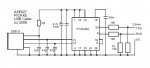
Obviously you are not using an AXE027 since it does not bring out 5V that can supply the Picaxe & peripheral circuitry For lack of other details , I am assuming a cheapo "FTDI" adapter purchased online since "cheap" seems to the the primary specification for many folks these days. Hopefully you included some kind of fuse or other current protection on the board in case of a mishap. If the adapter has a jumper to set the I/O level to 3.3V, beware as the 3.3V supply is limited to about 50ma max.I'm not using the 10K and/or 22k resistor(s)
Using USB FDTI adaptors .........
Seems to work fine .........
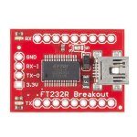
Genuine FTDI chips are laser etched. If the chip on the adapter is is not laser etched then it is a fake/counterfeit.
One more addition that should also be noted that is seldom mentioned about the way the AXE027 hardware is configured, it has two pulldown resistors one on the Rx line and one on Tx line. This is important when receiving data from the Picaxe because without it the receiving device will detect a first byte data transmission that was not sent by the Picaxe. I've also had to add a 10K pulldown resistor to my ERF Rx line to stop this unwanted first byte data transmission occuring. This will show up on the Serial Terminal as a non printable character.
I have used FTDI breakout board with the same resistor setup as the AXE027 cable without anyother download circuitry attached and powering the Picaxe through the USB port. But first you must reprogram the FTDI using FT_Prog to invert the Rx and Tx signal lines.
I have used FTDI breakout board with the same resistor setup as the AXE027 cable without anyother download circuitry attached and powering the Picaxe through the USB port. But first you must reprogram the FTDI using FT_Prog to invert the Rx and Tx signal lines.
Attachments
-
 60.3 KB Views: 29
 -
 78.9 KB Views: 33
Last edited: