Using TIP120/125 on Picaxe18X / ADC question

Pfrogs

Member
Hi guys,

I want to use a Picaxe 18X to control an RGB array (48 RGB leds with common anode). I want to be able to switch on-off each R, G and B channel independetly with 3 individual push-button switches and control the brightness (all channels at same time through common anode by PWM) using 2 individual push-button switches (one for increasing brightness and other to decrease).
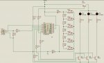
Since my array will be drawing 960mA to 2880mA (each LED draws 20mA/color), I decided to use a Darlington transistor TIP125 to control the anode PWM and a TIP120 to control each RGB channel cathode.
So in the end I have designed the attached circuit to do the job and the following program to run the picaxe.
init:
pwmout 3,64,255
b1 = 255

main:
readadc 0,b0
if b0 >= 36 and b0 < 72 then red_led
pause 50
if b0 >= 72 and b0 < 108 then green_led
pause 50
if b0 >= 108 and b0 < 144 then blue_led
pause 50
if b0 >= 144 and b0 < 180 then white_led
pause 50
if b0 >= 180 and b0 < 216 then dec_bright
pause 50
if b0 >= 216 and b0 < 255 then inc_bright
pause 50
goto main

red_led:
toggle 0
goto main

green_led:
toggle 1
goto main

blue_led:
toggle 2
goto main

white_led:
high 0,1,2
goto main

dec_bright:
if b1 = 0 then main
b1 = b1 - 5
pwmout 3,64,b1
goto main

inc_bright:
if b1 = 255 then main
b1 = b1 + 5
pwmout 3,64,b1
goto main
I have tested it and two issues came up.

1º The TIP125/TIP120 are not drawing as much current as I wished (~3A for white color). I know that maybe that has to do with the resistor I am using at the base, nevertheless I need help on how can I calculate the right resistor for this transistor to be fully open (I didn't wanted to experiment different resistors in my prototype so that I didn't damage the picaxe or any other component..first I want to learn how can I calculate things to go right, then experiment..have read several stuff about this but still don't understand much what the TIP125/120 parameters mean and how can I use them to calculate the right resistor).

2º The values I am getting from Readadc are to low (they go from 0 to 23). My questions are: Is the push-button/resistors part of the circuit well done or is there something wrong about how I am doing it? Or on other hand, how can I calculate the right resistors so that I can get a better linear range of readadc (i.e. from 0 to 255, equally divided by the 6 push-button switches)? Also, I am getting a huge delay (about 1 sec) in response from when I press the button and the debug value in my computer/response in circuit. Is this normal? I've tried to increase the value to 500 or just remove the "pause" function but that didn't solve the problem (in fact, when removed, it started to be instable due to the bounce effect).

Well, I'm sorry if this was a big message, but I wanted to explain all in detail so that anyone could help me with this issues.All help will be appreciated. If I forgot any relevant info to solve the problems I'm having, please let me know.
Thank you!
Pfrogs

Ps: I don't understand much about electronics, I only do it as a hobby, so please be gentle if these questions are to basic ;)
 

Attachments

Jeremy Leach

Senior Member
Well I think it's almost there, and nice schematic ! My suggestions would be to ...

Get rid of R9 so the ADC values can cover the whole range 0 to 5V.

I haven't done the maths on your resistor ladder but can't see anything wrong with it. Except I'd replace R4,5,6,7,8,10 with, say, 2K resistors. I think the 10ks are too high for the ADC input to read the voltage properly.

Not sure about the 1 second delay, but I think you should get rid of all the pause 50 in your code and just have one pause directly after Main:, I can't understand why you did lots of pause 50s??

Oh, and in your range calculations allow for some tolerance of the resitor values.

Personally I'd just experiment with the resistor values for the transistors - quicker probably ;) There will be lots of info on the net about calculating though. I'd guess you need to drop the values of R11 to R13 though, and the base resistors are ok.
 
Last edited:

BeanieBots

Moderator
A TIP120 is a darlington transistor. That means it has very high gain (hfe=1000) but at the expense of a high volt drop. 3v @ 0.5A according to the datasheet.
Working backwards from say 3A load current.
3A/1000 = 3mA required base current.
From V=I.R, R=V/I = (5v-3v)/3mA = 667R. Would suggest 560R for your base drive resistors.

Agree with Jez on the resistor ladder.
 

Pfrogs

Member
Thank you guys!
Jeremy: I will follow your suggestion and change the 10k resistors for 2k or even 1k, and remove the R9. About the "pause 50"s I now realize that it actually doesn't make any sense in having a bunch of them..I guess I was to worried about the bounce effect that I ended up complicating what is simple.
Beanie: Thank you so much for the calculations. I had actually tried doing those calculations but I was using a different voltage drop (0.7V,got this value somewhere in the internet), so when I did the calculations it would give me a 1k4.

I will get back to you once I've tried these changes. Hopefully, my problems will be solved. :)
Thank you once again!
Pfrogs
 

westaust55

Moderator
resistor values for RGB LED display

Pfrogs,

I am also slowly constructing a RGB LED module initially with an 8 x a matrix in a bax that should enable me to expand to 14 x 8 later.
I am multiplexing so my configuration differs from what youa re doing.
have a look at the thread here: http://www.picaxeforum.co.uk/showthread.php?t=10836

At post 13 is an excel spreadsheet I set up to calculate the values of resistors I needed based on one row of LED’s on at a time. IT looks at the volt drop across the two transistors involved and forward volt drop of the LED’s.
While this gets you into the right region, you will need to play around a bit with resistor values to get a good colour balance and white balance.
 

Pfrogs

Member
Thank you westaust! I've looked into it but I couldn't find the calculator you mentioned, just a pdf in post#17. The .xls (RGB LED display Calculator Rev_C.dsn) file from post#13 is just an array display calculator.

Anyways, I've tried substituting the resistors R4,5,6,7 and 8 to 1k and removed R9, as sugested, and it worked like a charm. I can now read the following ADC values (SW are the push-buttons): SW1:255; SW2:128; SW3:85; SW4:64; SW5:51; SW6:43.

I have also tried changing the resistors R3, R14, R15 and R16 to 460ohm (I have calculated this value from 4.5V DC which is what I am using..so (4.5-3)/0.003=500ohm). However, I still can't get the TIP125/120 to draw full power. If I measure the current drawn to light just one colour (48leds), I get a base current of 5mA but the emitter is just drawing 140mA?!? If I connect the power supply straight to the array I can measure 960mA.
Can this be do to the resistor values I have connected to each cathode RGB led on the array (Red Vfw=2.1V, 120ohm;Green Vfw=3.6V, 45ohm; Blue Vfw=3.6V, 45ohm)? Unfortunatly, I can't change this, so if this is the problem how can I solve it? Can I just rise the power supply so that it compensates the transistor voltage drop (ex. 4.5V + 3V = 7.5V power supply needed).
Or am I missing something about the transistor base resistor calculation? How come I can't get the transistor to open fully and draw the 20mA/each color/led?
Thank you for your help so far.
Pfrogs
 

westaust55

Moderator
to keep the transistor heating and voltdrop down the best way is to drive the transistor into saturation when used for switching functions.

TIP120 has a gain (Hfe) of 1000 (from Fairchild datasheet), so for 1000mA of current you need 1000/1000 = 1mA base current. Allowing for 1.5V emitter to base and 0.2V PIAXE output to supply rail then you will have a voltage of 4.5 &#8211; (1.5 + 0.2) = 2.8V across the base resistor. From V = IR you can work out a suitable resistor value. Then go down to the next standard size maybe even two sizes down go better get into saturation.

I have just up-loaded my resistor calculator spreadsheet onto the thread I mentioned earlier so have a look at the (currently) last post there.

Your supply voltage does need to take into account Vce or Vec so you need to look at the datasheets for that value as well.


EDIT:
Thinking &#8220;aloud&#8221; here but with just a 4.5V supply and two series transistors I am guessing that you have your LED&#8217;s in parallel. Each will need its own resistor otherweise they will most likely have imbalance in current and therefore lighting level between the various LED&#8217;s
 
Last edited:

LizzieB

Senior Member
TIP120 is a Darlington so the Base Emitter voltage will be more like 1.5 volts. I would drive it a harder than you are suggesting to ensure saturation, something like assuming 25% of beta.
 

Jeremy Leach

Senior Member
I have connected to each cathode RGB led on the array (Red Vfw=2.1V, 120ohm;Green Vfw=3.6V, 45ohm; Blue Vfw=3.6V, 45ohm)?
Can you explain exactly what voltages you measured here? I'm a bit confused. If these are the voltage drops required across the array, at 960mA, then I think you are stuffed using a 4.5V supply and two series transistors. Although maybe another type of transistor (FET?) would work.
 
Last edited:

westaust55

Moderator
Good point Jeremy.
Missed that when I corrected my earlier Veb voltages (more voltage across emitter to base) in line with Lizzies info and revisiting the TIP120 datasheet when looking at base drive resistor.


RGB LED's I recently received were "published as having Vf of Red = 2V, B & G both 3.5V
but the Vf measured over several samples gave R = 1.7V and B = 2.7V & G = 3.0V
My RGB matrix is operating at 5V for small portion built up on a breadboard for initial testing.
With that voltage and BC559 + BC338 transistors and much less current flow I have as little as 0.8V available across some resistors.

As you suggest, a different transistor or a higher voltage will be necessary.
4.5V sounds like 3 x battery cells which, if AA cells, will not last long with around 1 Amp per colour (or up to 2.8Amps for full matrix).
Plug pack (wall wart) at 5V may just work or 6V better.
 
Last edited:

Michael 2727

Senior Member
I was thinking a logic level MOSFET may be a better solution also.
Darlingtons have high gains but there is the voltage drop trade-off.
With a MOSFET the gain issues are usually removed "thats why I like them"
but they have their own quirky issues as well.

Seeing that you using a digital output (PWM) you should be running any Transistor/s
at full saturation, this is where MOSFETs shine (pardon the pun) needing only voltage
and very little current to switch ON fully.

Whatever works best in your application though is the winner :)
 

BeanieBots

Moderator
Lot's of echos going on here.
Not sure which datasheet people have been getting their figures from so here's one.
http://www.learn-c.com/tip120.pdf
Vbe @ 3A = 2.5v.
Vce @ 3A = 2v.

I've not looked up the PNP version but would expect similar figures.
Does suggest that FETs would be a much better option.
 
Last edited:

LizzieB

Senior Member
Not to split hairs but I think you are quoting the Maximum VBE(on) from that datasheet which is measured with VCE forced to 3V, i.e. the transistor is not allowed to saturate. Doesn't change the conclusion though, any way you look at it a FET is a better option.
 

Pfrogs

Member
Hi guys,

thank you all for your help. Trying to keep up with all replies...
yes, I have my 6x8 array = 48 RGB leds connected in parallel (their are common anode, so I guess I couldn't connect them in series if I wanted to control color mix). In each led I have a resistor for each color cathode (I did it this way so to better spread the eventual heating..don't know if this was the correct way to do it). The Vf I mentioned earlier are the ones that I got from the datasheet..i didn't actually measured them.
I am using 3xAA as power suplly and I realize that at full power (white color) I will be drawing around 3A, which will not give me much autonomy. Nevertheless, the application I want for this array, will only require it to be on for short periods of time (around 10min/week). And I am also considering having a 4.5V DC plug supply option.

I recon that all agree that a FET is a better option for my apllication.
I've had a look at some FET options and in the end I have selected the following:
IRF530 to substitute TIP120 in initial circuit.
IRF5305 to substitute TIP125 in initial circuit.
What do you guys think of these FETs? Will they do the job or do you recommend any other FET?
I also think that if I substitute the darligton transistors (TIP120/125) with this MOSFETs I will no longer need the picaxe-to-gate resistor. I'm I right?
Looking forward for your replies and thank you all for all the help so far!

Pfrogs
 

Jeremy Leach

Senior Member
I'm not as experienced as the analogue design experts on this forum - but I've always understood that you still need a gate resistor to limit inrush current. Basically the gate has capacitance and in theory you get very high current when you change the gate voltage - so you need a resistor to limit this inrush current. I'll let others advise over the FET characteristics ;)
 

Pfrogs

Member
Thanks Jeremy!
I also share your ideia, nevertheless my doubts on if I actually need to use a resistor at the base of the MOSFET came from the example you can see in Picaxe Manual #3, pg7. I'm aware that they suggest the use of a 100k pulldown resistor on sensitive circuits, but I'm not so sure my circuit is such an example. Also, isn't a 100k resistor too high?

Pfrogs
 

Jeremy Leach

Senior Member
Yes I'd say 100K is way too high. Someone might say I'm talking rubbish here, but if we're talking 5Vish supply, and let's say we want to limit inrush current to say 20mA, then the resistor (to cover worst case sudden 5V change on gate of FET) would need to be 5/.020 = 250 Ohms. Ish !

EDIT: Ah, just read that page of the manual. That's for a different reason. That's when the picaxe resets - the FET input could be left floating - which is a bad idea because static on the gate could damage the FET. There's two questions all this generates: 1) The example circuit on page 7 doesn't have a resistor to limit inrush current - is this ok then? and 2) is it always good practice to tie a FET gate, that's driven from a chip output, to ground via a large value resistor?

Perhaps someone can clarify this for us !
 
Last edited:

westaust55

Moderator
Lot's of echos going on here.
Not sure which datasheet people have been getting their figures from so here's one.
http://www.learn-c.com/tip120.pdf
Vbe @ 3A = 2.5v.
Vce @ 3A = 2v.
referring back to the datasheet (I have the same one)
Also if you look at the Vce(sat) data in the datasheet further:
Vce(sat) @ 5A = 4V max
Vce(sat) @ 3A = 2V max
so at an intended ~1A should be slightly lower, say around 1.5V max.
a "typical" (as opposed to max) value may be a little less again.

but with 2 x 1.5V drop across the resistors that does not leave enough for the LED's, so the FET suggestion or higher supply voltage is required.
 
Last edited:

Michael 2727

Senior Member
You will probably be looking at a TO-220 package MOSFET (usually 4A to 50A rated)
and a Logic Level device would be better, as they are guaranteed to switch fully at
Logic Voltage levels on the Gate, this roughly translates to-
(4.5V to 5V Supply) Logic Level Low = 1/3 supply, Logic Level Hi = 2/3 supply.

Most other mosfets are guaranteed to switch ON fully at 10V but many will start to
turn ON at 2V, 3V or 4V and if you are only drawing 1 Amp or 2 they are as good as
fully ON. It's when you want to draw the full rated current, say 12A or 32A that the
device may need 7V, 8V or 9V on the Gate to be fully ON.
With insufficient Gate voltage for the current required a MOSFET will behave more
like a BJT transistor and will get fairly hot, then you may need a large heatsink.
(they still work but it defeats the whole purpose really)
Look @ Fig: 2 on the IRF5305 data sheet, Gate Voltage vs Current.

Quite often it will come down to what is commonly available to you and price etc.
It also has to do the job requierd :)

Always use a Gate resistor, even though it may not have any real effect the
function of the circuit, it will prevent a failed/shorted MOSFET sending the supply
voltage back into the Picaxe output. Try 330R to 1K for safety.
Some applications could use 12V, 15V, 24V or more through the MOSFET which will
instantly kill a Picaxe if the device fails-short.
 

westaust55

Moderator
Think that you will find a series resistor alone with not protect the PICAXE in the event of an FET fault. It can limit the current but not the voltage. You need a potential divider to do anything definite about the voltage.

Have been there done that before. Tried to get away with a single resistor in a 5V to 3V application and calc'ed a resistor value based on around 0.5mA current flow which gave 4.7kOhm. When the PICAXE output went high (to 5V) it forced the entire 3V IC to 5V on the Vdd pin and the outputs.

Sure, a FET fault in the case under this thread is in the opposite direction, that is back to the PICAXE but same applies when a second voltage level is involved.

Completely different to protecting against a short at the non PICAXE end of a resistor to ground or PICAXE Vdd level.
 

alband

Senior Member
Hello everyone.
I suspect all these desgusions about transistors will have gone on for a reason and that I've missed something, but just in case...
Wouldn't it be easier to just connect the cathodes to an output pin and pull it low when needed? This is what most LED drivers do such as the LM3914. :confused:
 

Michael 2727

Senior Member
The Gate input/pulldown question in here is a Hairy Minefield, Jeremy has wisely opted
out of answering it, I won't either, I don't want to start a 1000+ post thread.

In some cases you may need a Gate pulldown resistor to ensure the MOSFET turns off
correctly or fast/er, this resistor can be as high as 1Meg for simple switching.

It's when you get into Higher current, Higher Frequency applications that you need
to wory about input capacitance, inrush and turn ON/OFF times etc.

PWM at a few KHz and only driving 1 Amp or so for RGB LEDs is not rocket science
so don't be too concerned about everything you hear/see.
Try a 100K pulldown if you like, but anything between 20K to 200K will prolly work
just as well.

I didn't like the sound of the 3 x AAAs either,, way underated for this Application.
(will you even get 10 mins @ 3A from a set of AAAs ?)
You may be hard pressed to find a 5V supply capable of more than 1A or so.
If it's rated @ 1A and you draw 1A it probably run very hot and won't last long.
My own rule of Thumb for power supplies is 60% duty MAX
An old PC supply hidden under the bench will look just as neat :)
If AC is not available a 7.0AH SLA Battery would be a much better option.
 
Last edited:

BeanieBots

Moderator
Agree 100% with Michael 2727.
In THIS application, a resistor of about 1k between PICAXE and FET would be fine. The PICAXE output can easily cope with the capacitance charge currents and at the low frequency PWM used, turn on/off times are not a problem either. I've proved this with my Pb charger/discharger project. In fact, that was almost the only reason I did that project. To end this debate (one way or the other) with some cold hard facts.

Very much doubt you would get more than about 3 mins TOTAL out of AAA batteries at 3A. Consider NiMh type with wall-wart constant charge for short duration high current. (a bit like a very large cap).
 
Top