Using the XBee "Off the Shelf"

GDSever

Member
My second XBee unit is arriving today from SparkFun (they accidently shorted me one in the original shipment), and I'm going to start playing them sometime really soon... My question is in regards to the AXE210 datasheet guidance of first configuring the baud rate between PICAXE and XBee to 2400... Is this really necessary?

Seems to me that rather than modifying the XBee config, an alternative would be to kick the resonator frequency up to 8Mhz and send data to/from the XBee using the 4800 baud serin / serout parameter... and then if necessary I could drop back to 4Mhz after the serin / serout commands. This should allow the XBee to talk with the Picaxe using its standard "off the shelf" configuration of 9600 baud... I think.

Am I missing something in this approach that would make it less favorable than running everything at 2400 baud?
 

hippy

Ex-Staff (retired)
Staff member
You can use the XBee at any baud rate you want. At higher baud rates it can get harder for the PICAXE to keep up with data received from an XBee so a slower 2400 baud is 'recommended' but not always necessary.

The baud rate only affects the rate at which data gets passed between the PICAXE and XBee, between two XBee's it's done at 'super-high speed' regardless. It's possible to configure each side of an XBee link at different baud rates and that will work okay.
 

GDSever

Member
Thanks guys. I just realized I'm hosed anyways, since my XBee modules are the 2.5 ones... and it looks like I need the ability to upgrade the firmware on one of the chips to act as a coordinator. Isn't gonna happen with my AXE210 module, and I'm not comfortable enough with the modules to breadboard something...

Frustrating when you think you've got everything ready to go, and another gotcha pops up.
 

hippy

Ex-Staff (retired)
Staff member
The XBee range gets more confusing every time I go to the manuafacturer's site ...

http://www.digi.com/technology/wireless/products.jsp

1) XBee® ZB ZigBee® PRO Radio Modems
2) XBee® ZNet 2.5 Radio Modems
3) XBee® 802.15.4 Radio Modems
4) XBee-PRO® 802.15.4 RF Modems

The 'original XBee modules' Rev-Ed used to ship were the third kind which don't support the later 'clever networking stuff' and are incompatible with those that do, but compatible with (4).

If you've got the second that should support co-ordinators AFAIR but I admit I have completely lost track of what MaxStream / Digi are doing.
 

moxhamj

New Member
Agree Hippy - it gets more and more confusing. I got so confused I built my own because it is easier to understand picaxe and vb.net code than to understand the xbee manual.

All credit to Rev Ed for this - they have a knack of taking complex problems and making them simple. And lots of simple concepts = a working project.

I'm just in the final testing of my wireless mesh project. I have 9 wireless nodes all chatting at the moment and I'm just testing the dynamic stability of the network. In medical terms, just checking there are no epileptic seizures in the network.

Much longer range than xbee - 500 metres between nodes. And cheaper. I'll publish once it is stable.

And once that is working - next project is high speed dynamically assigned RS232 wireless links between arbitrary nodes. So you can set up a link between two nodes at 4800 baud (at least) and there can be intermediate nodes but the user doesn't need to worry about that. I'm working towards a wireless network of CPM computers. CPM is cool. 1978 Micro-Soft basic has a lot more commands than picaxe basic (floating point maths, strings, file load and save etc), and it can be compiled on its own computer.

Picaxe still remains critical to the mix - these sorts of hybrid retro/new projects would not work without picaxe.

As Hippy says, one big problem is picaxe keeping up with xbee (or any module really). I'm working on a hybrid Z80/picaxe board that can solve that problem so it is possible to buffer in kilobytes of data rather than bytes.

Meanwhile, if you want a practical solution for picaxe, keep the packets 14 bytes or less.
 
Last edited:

GDSever

Member
Tell me about it. I didn't realize using the 2.5 modules in place of the 1.0 would be an issue until I started reading through the new documentation. There is a note on the SparkFun site indicating the 1.0s and 2.5s are incompatible, however I did not see any indication that the AXE210 couldn't support all the functionality required by the 2.5s...

All this started off with me looking at some 315Mhz modules that appeared promising, but once I started testing them I realized that they did not provide the kind of reliability I wanted... unless I slapped a big antenna on every unit, and that kind of defeated the purpose of me looking at wireless in the first place (fewer tripping hazards, etc).

http://brewznet.wordpress.com/2008/07/27/wireless/

I improved transmissions a little using some of the guidance from Dr. Acula's instructables, namely the manchester coding where every byte is sent with an inverse value to balance the 1s and 0s, but in the end - it still wasn't reliable enough for me to feel comfortable with them as a viable option.

Hence the XBees - they're significantly more expensive and probably overkill for the application, but I hoped they would prove more reliable. I guess that this all may be end up a $200 failed experiment and I have to fall back to my hard-wired approach... C'est la vie.
 

papaof2

Senior Member
Maybe use the XBees to control a wireless robot to bring you a cold one at the end of the day?

Or find some penny-pinching PICAXE experimenter who'll offer 10 cents on the dollar (my hand goes up ;-)

John
 

hippy

Ex-Staff (retired)
Staff member
Tell me about it. I didn't realize using the 2.5 modules in place of the 1.0 would be an issue until I started reading through the new documentation. There is a note on the SparkFun site indicating the 1.0s and 2.5s are incompatible, however I did not see any indication that the AXE210 couldn't support all the functionality required by the 2.5s...
The AXE210 should support all XBee modules although there's an issue with the regulator needing replacing depending on how much current each XBee type demands. The incompatibilities are within the XBee itself and how they communicate with each other. With any two XBee's of the same type they should communicate straight out the box and with minimal configuration link two PICAXE's together - at least that's my understanding of it.

As an aside : Which XBee modules are Rev-Ed shipping these days ? The image on the Tech-Supplies site is of the original XBee non-PRO module.
 

GDSever

Member
If you're just building a point-to-point link any two XBee of the same type should be able to do what you need, although I admit I don't have practical experience of that except with the original XBee modules.
Well, my ultimate design would actually require 4 different XBees all working together, so its not just 2... But I could at least start playing if 2 would communicate out-of-the-box.

Time to chase the vultures away... they appear tp be circling, ready to pick over the carcass of a potential failure... SHOO!!! SHOO!! ;)
 

moxhamj

New Member
I've tried zooming in on your laptop/protoboard setup, and maybe it is the zoom, but I can't see any antennas on your modules?

It doesn't matter what you do with RF - you have to have an antenna!

Range without one will be a few centimetres. You will get a bit of range as the power supply leads will act as an antenna, but it is all fake range and it will sort of work on the bench but not out in the field.

Those modules should go 100s of metres and with 100% reliability.

An antenna for 315Mhz is just a piece of wire 23.8cm long at 315Mhz. If space is a problem, wind the antenna round a pencil and you can shrink it down.
 

Wrenow

Senior Member
By the way, has anyone tried the Nordic modules also available from Sparkfun? Less expensive than the XBee, more range in some models. Burst mode communication and some other attractive looking features.

Cheers,

Wreno
 

GDSever

Member
I've tried zooming in on your laptop/protoboard setup, and maybe it is the zoom, but I can't see any antennas on your modules?
You are right for that picture. I tried several different antennas after that picture was taken, some longer than 23.8cm, some shorter - I can't say that I tried exactly 23.8cm. While the antennas seemed to improve communications somewhat... the modules still lost a good 80% of the transmissions.

I know I could probably make even more improvements with the 315MHz given enough time, but that is not really a factor I have alot of (with twin 5-year old children)... so the XBees with an integrated chip antenna looked like a good idea.
 

moxhamj

New Member
Hmm - no time...

Have you got the xbees working yet? If yes - pls post a step by step guide as others will certainly be interested.

If no, then you can look at different modules, look at the Hope transceivers http://www.picaxeforum.co.uk/showthread.php?t=9048&highlight=hope+rf+module or go back and try your existing modules with antennas.

Pretty much all the modules I have played with will not work under 1 metre apart. I think the RF input stage gets overloaded. But 3-4 metres and they work fine.

Also, what sort of code were you using? How many wakeup "U"s? A checksum?

What is your space criteria? If it has to be very small - 2.4ghz could be an option. What sort of range do you need?
 

GDSever

Member
Hmm - no time...

Have you got the xbees working yet? If yes - pls post a step by step guide as others will certainly be interested.

If no, then you can look at different modules, look at the Hope transceivers http://www.picaxeforum.co.uk/showthread.php?t=9048&highlight=hope+rf+module or go back and try your existing modules with antennas.

Pretty much all the modules I have played with will not work under 1 metre apart. I think the RF input stage gets overloaded. But 3-4 metres and they work fine.

Also, what sort of code were you using? How many wakeup "U"s? A checksum?

What is your space criteria? If it has to be very small - 2.4ghz could be an option. What sort of range do you need?
No, my second XBee that was supposed to arrive yesterday got rescheduled to today... so I have not had any opportunity to work with them. Once I've got things ironed out and can compose a coherent instruction document, I'll do so.

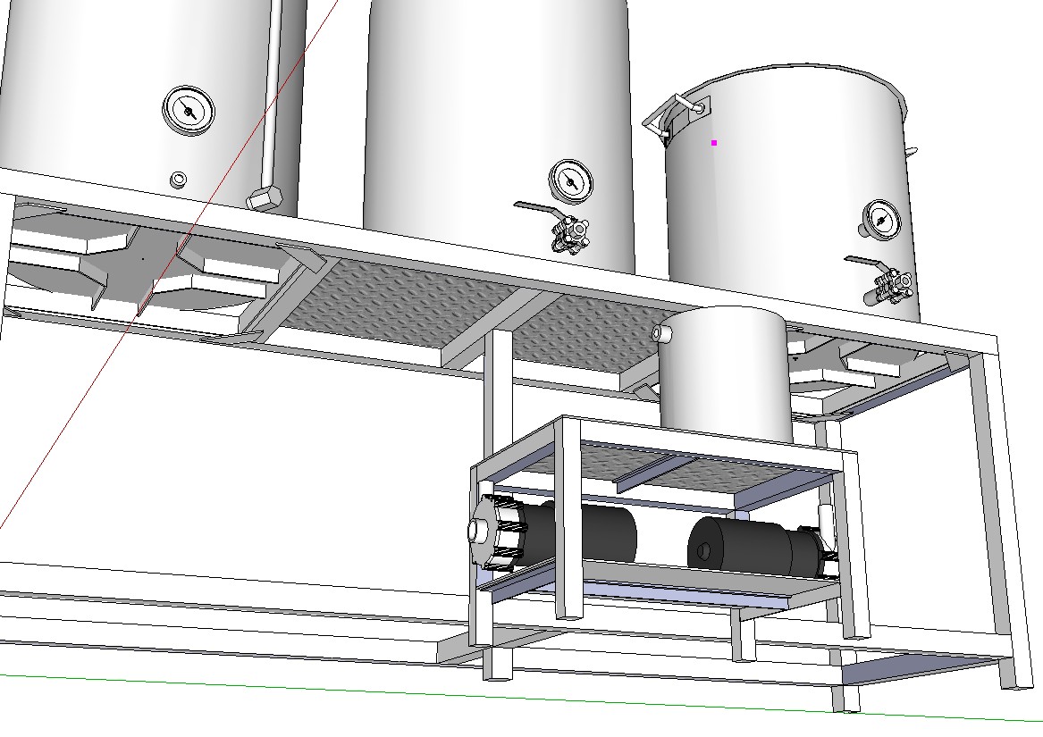
OK. Time to lay the cards on the table - Here's some of the project details, for those that haven't read through my blog posts. My modules will all be spaced relatively close together, definitely <4m. In the case of the grant and pump control module cited in the blog post, that will be typically 20-40cm, at most (the stainless steel vessel with the float switches will set on top of a stool-like structure, while the control box for the pumps sits just underneath that top surface on a shelf). There will be a third module on the main sculpture that controls propane burners and takes additional sensor readings (temperature, pressure, level switches) and shares some information back and forth with the pump control box. A fourth module will external to these three and basically logs all the data to a SQL Server database (as well as trend and display the data).


I know - you're wondering why bother for something as short as 20-40cm when the hard wire would be short as well. When you are dealing with water / fire / electricity all together in the same application, minimizing exposed wires and panel penetrations as well as decoupling systems that could "short" seems like a really good idea. I may still hard-wire... I'm still exploring options at this phase.

As a sanity check I might have to test the 315Mhz modules again and space them much further apart (2-3m, as you say). At least that will show they can work correctly, although they are the wrong component for this particular application. I was using your approach (including the "U" and checksum) from the "Under $40" instructable - so hopefully that aspect was not the issue.
 

hippy

Ex-Staff (retired)
Staff member
When you are dealing with water / fire / electricity all together in the same application, minimizing exposed wires and panel penetrations as well as decoupling systems that could "short" seems like a really good idea. I may still hard-wire... I'm still exploring options at this phase.
Are you just monitoring or also controlling via wireless ? If controlling I'd have thought that hard-wired would be a much safer and more reliable proposition.

Also, if having to bring wiring from sensors out to the wireless modules, isn't it easier to just make that cabling longer ? With a wireless system you're going to have to get power to the transmitters and that's going to likely need cabling back to a central point anyway. Presumably there is already cabling going into the system so I don't really see what you're gaining, apart from unnecessary complexity.
 
Last edited:

moxhamj

New Member
Good point Hippy - if you already have power then why not add a few more wires for data? 2 wires for power, two for data. For 4 metres, probably not even worth converting with a max232.

If it is all battery powered, then failure modes would need to be considered if the batteries fail. Eg will the data change as the battery is almost flat, or will it suddenly stop sending data, or will it sense the battery and send warnings.

Also, that instructable used high power 315Mhz modules. Which ones are you using? Because the higher the power, the longer the "minimum" distance. The 1 watt 500 metre modules won't send anything under 10 metres. (even computer monitors go wavy when the module is transmitting!) For 4 metres, 10mW would be perfect, and that power rating happens to be the cheapest modules as well. Only $2-3.

Stan has a simple version of code etc at http://picaxe.orconhosting.net.nz/433rpt.jpg And curled up antennas as well. Small enough to fit in a plastic box with the antenna inside the box.
 
Last edited:

GDSever

Member
Are you just monitoring or also controlling via wireless ? If controlling I'd have thought that hard-wired would be a much safer and more reliable proposition.

Also, if having to bring wiring from sensors out to the wireless modules, isn't it easier to just make that cabling longer ? With a wireless system you're going to have to get power to the transmitters and that's going to likely need cabling back to a central point anyway. Presumably there is already cabling going into the system so I don't really see what you're gaining, apart from unnecessary complexity.
All good points, and ones I've argued with myself over.

Regarding controlling, I'm doing everything I can to localize required functionality... basically this will be a PICAXE powered distributed control system (DCS). Functionality required to run the pumps will be on the pump skid and controlled locally... Functionality required on the main part of the sculpture is located on the sculpture and controlled locally... and all by hardware, not software. My original vision included PC-driven control, but I've heard enough horror stories about Windows crashes and other issues that I quickly abandoned that idea. I'm not opposed to the idea of sending setpoint updates out to the individual control systems (following a DCS model)... but controlling to the setpoints would be local hardware responsibility.

Regarding power, my intent for the wireless approach was to use a battery source for the grant. The pumps themselves require around 9A service, so I was planning on using a Cosel VAA505 to convert the 120VAC to 5VDC to power the control box circuit (since I have it running in there to the SSRs anyways). Since we're primarily discussing the link between the grant and the control box, yes - Wireless is a completely unnecessary complication. An 8 conductor wire like CAT5 cable could very easily carry 5V and GND out to the grant and bring the LM34 and 2 digital float switch signals back... A 3 conductor cord could also work if I sent information from the grant to the control box as a serial communication.

And yes, before anyone brings it up, everything will be GFCI protected. Mains will not be exposed. Trying to be as code compliant as I can be, given the "homebrewing" nature of this. Safety is foremost in my mind... If electricity doesn't kill me, the propane tanks or boiling water could also, or a combination of the three. Fortunately I work for a chemical company that subjects us daily to safety messages and meetings.

The 315Mhz modules came from SparkFun and were around $9/ea. They most likely are not high-powered. I was providing a VCC of 5V, so its not like they were getting alot of juice anyways... I didn't figure they needed it for a distance of a few feet.
 

GDSever

Member
Well, after some testing it appears that the 2.5 chips will not communicate with one another without having the coordinator firmware loaded on one of them. I am planning or ordering the XBee explorer unit from SparkFun (which appears to give me the ability to upgrade firmware).

Disappointing that the AXE210 can't be used exclusively to set up an XBee network anymore... although its not really RevEd that changed the game here.

On another note - the 9V to 5V regulator in my AXE210 totally crapped out today after very little use. Fine for a few days them blam! None of the LEDs were lighting up anymore. After spending several hours cursing and totally convinced I had assembled the unit incorrectly or fried my XBee modules, I swapped out the 9V connection with a 5V regulated supply from the adjacent breadboard and voila - things started working again. The download to the 18X chip still worked fine with a 9V connection, but for some reason the 3.3V regulator for the XBee was not getting the kind of input voltage it needed. I suspect the 9V -> 5V is putting out something <4V right now, something that the Picaxe barely works on... but I need to go out and get a new VOM meter to confirm (don't ask what happened to the old one...)

Anyone else had their AXE210 9V->5V regulator go bad on them?
 
Top