Using pulsin to measure frequency

sbscott

Senior Member
Greetings,
I want to add an ability to measure wind speed using the 18x and have searched the site for others who have worked on this. Found several threads but what I am looking for is a simple (if it can be made simple) short block of code using PULSIN to measure frequency. I have tried several things measuring my oscillator output but get nothing when I try to read the value from PULSIN.

Any short code out there?
 

BeanieBots

Moderator
Impossible to give any sort of code example without knowing some numbers from yourself, except to say the obvious which is that pulse width is inversely proportional to speed.

What is the nature of the signal you are using?
What sort of rpm do you need to measure?

Depending on your encoder type or whatever you are using to measure speed, it might not be possible to use pulsin and you may need to go with Andrew's suggestion of count. If you have a tacho fitted, then ReadADC would be an option.
 

domwild

Member
Here is a piece of code for the Fisher & Paykel RPM measurement BUT it has not been tested as yet. May give you some ideas, though. Uses COUNT and PULSIN.

Beware! UNTESTED!


'*** READING PULSE LENGTH, THEN CALC ONE REVOLUTION, 14 magnets = 28 half pulses
'*** ALSO SWITCH ON THE STAR/DELTA RELAY, NC POSITION ON 4P2T RELAY IS STAR SETTING

rev: pulsin 1, 1, rpm 'measure one pulse (lo/hi) in 10 usec units
if rpm > 0 then 'prop turning
rpm = rpm * 28/100 '28 pulses/rev, 10 usec units, 1 rev in msec
rpm = 60000 / rpm 'how many in one minute?
count 1, 4000, rpm1 'double-check RPM - count pulses this time for 4 secs
rpm1 = rpm1 * 15/14 '15x4=60 sec, 14 pulses per rev.
noturn = 0 'reset for next sleep
if rpm > 200 AND delta = 0 then 'high RPM, switch on delta
delta = 1
high 2 'delta relay to ON, 3P2T
return
endif
if RPM < 180 AND delta = 1 then 'low RPM, delta on, now set to OFF
delta = 0
low 2 'relay off
return
endif

endif

inc noturn 'prop not turning
sleep noturn 'sleep for 2.3 x noturn secs, progressively longer
goto rev 'stay in loop here until prop turns, up to 41.8 hrs
return
 

westaust55

Moderator
Using COUNT to measure frequency

As Andrew has stated, IMHO the COUNT command is the easiest method.
If you can accept the 1 second =1000 milliseconds) delay then no maths required:

COUNT pin#, 1000, word_variable

will give you the frequency directly into the word variable when operating at 4MHz (standard PICAXE) clock speed.

I have used this to measure frequencies around 6kHz and from the manual it can go as high as 25kHz with a 50% duty cycle at a PICAXE clock speed of 4MHz.
 

sbscott

Senior Member
Ahhh, great responses! Thanks!
I am adding a "weather station" onto my house monitoring system using PICAXEs & a PC. I have a reed relay-based anemometer that I want to read. So the frequency will be low. I will try the "count" command and see how it works. Any other suggestions would be appreciated!
 

hippy

Ex-Staff (retired)
Once you have a signal from the anemometer you can use it with both COUNT and PULSIN so it's worth trying it and seeing what figures each return.

Presumably there will be an additional RPM to wind-speed equation which needs to be determined. It may be best to provide the information as a whole ( or at least all information and equations ) as that can help people determine a direct COUNT/PULSIN to wind-speed calculation with minimal errors and maximum accuracy.

COUNT is, as others suggest, probably the easiest to use, but PULSIN may be better if there is a 1/N in the equations somewhere.

As to why your current PULSIN doesn't work ( presumably always reading zero ), it could be that the frequency is too low ( below 1.5Hz ) or perhaps a circuit or wiring error. Your reed relay will need wiring like a switch so will need a pull-up or pull-down resistor.

Others more experienced with 'weather machines' will probably know more than me about how to protect against electrical noise and lightning strike.
 

sbscott

Senior Member
Using COUNT

After some false starts, I have COUNT working but the numbers I am seeing don't make much sense. I am generating a square wave that will range from '0' HZ to probably no more than 150 HZ. That would be a reed relay making and breaking with each revolution of the anemometer. I have to feed this into a gate to generate a clean signal to the 18x.
If this frequency is too low for the COUNT function, I can always double or quadruple the frequency by adding more magnets to the shaft.

I am varying the period to see how the numbers change as the frequency goes up but am not sure what I am seeing. I will work on it some more. If anyone has any experience, please speak up!

Thanks
 

womai

Senior Member
What exactly are you seeing? Are the measured pulse widths much smaller than expected? In this case signal noise and/or contact bounce could be the culprit. Have a look at this recent thread:

http://www.picaxeforum.co.uk/showthread.php?t=11938

To reduce noise, you could low-pass filter your signal with a simple R-C filter: Resistor R between signal source and Picace input, capacitor C between Picaxe input and GND. The time constant R x C should be a good bit smaller than the shortest period you want to measure. So for e.g. 200 Hz maximum you'd shoot for well under 5 msec; a value of 1 msec is a good bet - just use R=10 kOhm and C=100nF=0.1uF.

Wolfgang
 

sbscott

Senior Member
Ok. I have done some tests and the results suggest that I may not be able to use the COUNT function at the low frequencies generated by the anemometer

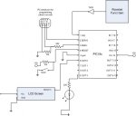
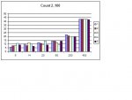
I set up a 18x with my function generator via an inverter to invert the square wave. I took measurements at 6, 14, 20, 60 200 and 400 Hz. I took these readings using different periods- 100, 250, 1000, and 3000.

Below 200 Hz, the readings bounced around. As you look at the attached graph, this occurs at all periods. Once I hit 200 Hz, the readings began to stabilize. The higher the freq. the more stable it became? It could be my funct gen, but it is a good one and the scope display looked stable.

I created a graph for each period sample but can only upload one so I uploaded the 100 period. The other period samples were similar although the higher the count value the more unstable the lower freqs. were.
This is the code I used:

b1=254
b2=1
st:
pause 100
SEROUT 0,n2400,(b1,b2)' clear LCD
pause 100
SEROUT 0,n2400,("press butt to st") 'start seq.
pause 100

main:
if pin1 =1 then goto measure
goto main

measure:
pause 100
SEROUT 0,n2400,(b1,b2)' clear LCD

count 2,100,b3 ' get measurement

pause 1000:high 3:pause 1000:low 3:pause 1000 'flash LED to indecate complete

serout 0,n2400,("count ",#b3)' send value to LCD
pause 4000
goto st ' start over


Any thoughts?
 

Attachments

Top