Andrei IRL
Senior Member
Hi everyone.
I am trying to improve a device by replacing a pair of mechanical relays with IRL540 MOSFETS.
Everything seems to be working at first.
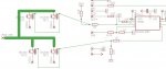
I am reading an input on PIN3. The signal is a 12v stepped down using voltage divider with 1Kohm and 2.2Kohm resistors.
When this signal is received on PIN3 then a routine is ran, which turns on OUTPUT4 and OUTPUT2 for a predetermined length of time.
Once that time is up both OUTPUT4 and OUTPUT2 go LOW.
The problem is, while i was using relays everything worked very well.
I removed the realys and NPN Transistors that were driving them and replaced them with IRL 540 MOSFETS.
It seems that now that the MOSFESTS power LEDS for a random length of time, almost as if the PICAXE gets RESET some times.
I have a delay set as to how often the MOSFETS can be powered, and its every 200ms, but some times i can not re-triger them for up to 1 sec.
Any idea what i might be doing wrong?
Thanks very much.
I am trying to improve a device by replacing a pair of mechanical relays with IRL540 MOSFETS.
Everything seems to be working at first.
I am reading an input on PIN3. The signal is a 12v stepped down using voltage divider with 1Kohm and 2.2Kohm resistors.
When this signal is received on PIN3 then a routine is ran, which turns on OUTPUT4 and OUTPUT2 for a predetermined length of time.
Once that time is up both OUTPUT4 and OUTPUT2 go LOW.
The problem is, while i was using relays everything worked very well.
I removed the realys and NPN Transistors that were driving them and replaced them with IRL 540 MOSFETS.
It seems that now that the MOSFESTS power LEDS for a random length of time, almost as if the PICAXE gets RESET some times.
I have a delay set as to how often the MOSFETS can be powered, and its every 200ms, but some times i can not re-triger them for up to 1 sec.
Any idea what i might be doing wrong?
Thanks very much.
Code:
low 4
low 2
Pause 1000
setfreq m8 ` Running at 8Mhz, all pause values are x2 times

symbol greenled=0 	`ready LED
symbol RELAY1=4
symbol RELAY2=2


main:       high greenled
		if pin3=1 then fire

goto main

fire:	     	high relay1
	     	high relay2
		low greenled
		pause 200
		low relay1
		low relay2
		pause 400		 `pause 200ms anti-bounce

goto main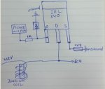
")