using comparators

jinx

Senior Member
hello all,
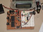
Am trying to get my head around the use of comparators. I had the idea of using two LDR (in a voltage divider setup as in manual 3) placing the signal wire of the ldr to b.2 which is comparator 2+
One on either side of of my bot a basic line detection. Having trouble in the simulator with the compset with the sim. saying "Interenal voltage reference for compsetup is not currently simulated". Am experimenting with 20x2 for now altough the code i written passes the syntax check i hav'nt programmed the picaxe for fear of damaging the pin. am sure this is the first of many error's:confused:
Code:
#picaxe 20x2


let adcsetup = %0000000000001000 ; set ADC4
compsetup %01101010,0            ; use comparators 2

setintflags %00010000,%00010000


symbol lsens = b.2     'comp2+
symbol led = b.7
symbol adcval = b1


main:

do
  readadc lsens,adcval
  SerTxd( #adcval, CR, LF )

 low led
 pause 10
  loop


interrupt:
   setintflags off
    compsetup 0,0
     pause 10
      sertxd ("warning left",cr,lf)
      gosub flash
      pause 10
      compsetup %0101010,0
       compflag = 0
       setintflags %00010000,%00010000
       pause 200
       return


flash:
   high led
    pause 200
     return
please point me in the right direction guys
thanks jinx
 

nick12ab

Senior Member
One on either side of of my bot a basic line detection. Having trouble in the simulator with the compset with the sim. saying "Interenal voltage reference for compsetup is not currently simulated". Am experimenting with 20x2 for now altough the code i written passes the syntax check i hav'nt programmed the picaxe for fear of damaging the pin.
It means exactly that - the simulator doesn't simulate the internal voltage reference for the comparator.

Downloading the program on to the chip won't damage it.

See also: This will calculate the command for you.
 

jinx

Senior Member
err.
Nick thanks for the link am sure this will be a very useful tool. "compsetup %0011000010, $80" I used your wizard i thought there where only nine bits used to set the comparators and the wizard produced ten bits. but i downloaded the code and you know it, It did'nt work can i use the comparator the way i mentioned the code most be completely wrong for what i wont to use it for as it did'nt trigger the interrupt as i aspected please help me what i am missing to get this to work.
thanks jinx

"please help me what i am missing" a brain i have one just ain't much bigger than a slug":eek:
 

jinx

Senior Member
hi srnet,
I just read and reread the manual and clicked to the ten bits sat with paper and pen:rolleyes:
 

nick12ab

Senior Member
Can you provide your complete schematic?

Anyway, if you want the 1.024V reference, the command is compsetup %1011000010, $0.
 

jinx

Senior Member
hi nick,
A complete schematic is bit tricky right now can offer a pic dont know if gonna be of any helpDSCF0073.JPG as its just one of my experiment boards and i,ve wired the ldr as if where a pot with the output going to the adc pin.
Anyway, if you want the 1.024V reference, the command is compsetup %1011000010, $0.
i,ve worked that bit out thanks but i see this has this bit has changed $80 to $0 why is that?.
 

jinx

Senior Member
well i modified the compsetup but the value's returned in adcval range 1 to 5 in the do - loop part,"I,ve tested the adc pin with a test prog that appears to be fine, nor does it trigger the interrupt.SO am stumped if this method is actauly going to work for me.
Code:
#picaxe 20x2


let adcsetup = %0000000000110000 ; set ADC5/ADC4
 compsetup %1011000010, $0       ; use comparators 2

setintflags %00010000,%00010000


symbol lsens = b.3     'comp2+ adc5
symbol led = b.7
symbol adcval = b1


main:

do
  readadc lsens,adcval
  SerTxd( #adcval, CR, LF )

 low led
pause 100
  loop


interrupt:
   setintflags off
    compsetup 0,0
     pause 10
      sertxd ("warning left",cr,lf)
      gosub flash
      pause 10
      compsetup %1011000010, $0
       compflag = 0
       setintflags %00010000,%00010000
       pause 200
       return


flash:
   high led
    pause 200
     return
 

jinx

Senior Member
morning all,for those in different time zone gd evening,gd day.
well my head has turned to mash, can i even use the adc pin to return a value from 0 to 255 when setting the comparators i,ve done a forum search using key words like LDR,compsetup,20x2 etc even googled the world lol it gave me a link too this thread there appears no one has used in the way i was thinking. So it's got me thinking that i totally misunderstand the use of comparators and can't be used this way. Any idea's would be helpful guys and girls.
thanks jinx
 

nick12ab

Senior Member
i,ve worked that bit out thanks but i see this has this bit has changed $80 to $0 why is that?.
If you're usinmg the FVR instead of the voltage divider, you don't need it enabled.

morning all,for those in different time zone gd evening,gd day.
well my head has turned to mash, can i even use the adc pin to return a value from 0 to 255 when setting the comparators i,ve done a forum search using key words like LDR,compsetup,20x2 etc even googled the world lol it gave me a link too this thread there appears no one has used in the way i was thinking. So it's got me thinking that i totally misunderstand the use of comparators and can't be used this way. Any idea's would be helpful guys and girls.
thanks jinx
When it's connected to the computer, are you using the RS232 download cable?
 

jinx

Senior Member
when i use this piece of code
Code:
symbol lsens = b.3     'comp2- adc5
symbol led = b.7
symbol adcval = b1


main:

do
  readadc lsens,adcval
  SerTxd( #adcval, CR, LF )

 low led
pause 100
  loop
the value return range 1 to 3 that it
but if i address the pin directly
Code:
main:

do
  readadc b.3,adcval
  SerTxd( #adcval, CR, LF )

 low led
pause 100
  loop
i get the value i aspect to see a range from 59 to 160 their about
but still not trigging the interrupt.
 

hippy

Ex-Staff (retired)
Also this post which touches on the differences between ADC channel numbering and port.pin to channel conversions ...

http://www.picaxeforum.co.uk/showthread.php?20244-Compiler-bug&p=192924&viewfull=1#post192924

Basically -

symbol lsens = b.3
readadc lsens,adcval

Is not the same as -

readadc b.3,adcval

The compiler does it's auto-magic conversion of port.pin to channel number in the second case, but not in the first.

From the pinout in Manual 1 for the 20X2, pin B.3 is ADC5, so these are all the same ...

readadc b.3,adcval

readadc 5,adcval

symbol lsens = 5
readadc lsens,adcval
 

jinx

Senior Member
hi all,
@allycat i have come across "kranenborg" thread really interesting but still digesting the method but my target picaxe is a 28x2 just testing on 20x2

@ hippy thanks for the reminder about ADC numbering "put a sticky on the wall till it sinks in".
I've added another " tidied up the breadbroad hopefully easyier to see my setup
DSCF0075.JPG
so i took a MM reading of the LDR divider it reads 2.2v under current lighting and 0.83v when covered which is well below the IVR
put still does'nt trigger the interrupt.
 

hippy

Ex-Staff (retired)
i took a MM reading of the LDR divider it reads 2.2v under current lighting and 0.83v when covered which is well below the IVR put still does'nt trigger the interrupt.
Start simpler; connect a pot across 0V/+V to the comparator input and use a simpler comparator setup and get that working first, keep the code as simple as possible.

Then move incrementally from that to what you actually want. Things will either progress smoothly or you'll have a "that all worked, this doesn't" and why that is will be much easier to analyse.
 

jinx

Senior Member
hippy will do
but am rerereading the compsetup i have no idea
bit3 = 0 Comparator 2 output is not inverted
= 1 Comparator 2 output is inverted
bit2 = 0 Comparator 1 output is not inverted
= 1 Comparator 1 output is inverted
what it means.
 

hippy

Ex-Staff (retired)
am rerereading the compsetup i have no idea what it means.
The comparators have two inputs "+" and "-" and like normal hardware comparators will output a high when "+" is greater than "-".

Setting bit2 or bit3 simply inverts the respective outputs so you get a low when "+" is greater than "-".
 

jinx

Senior Member
hi hippy, am still strugling with this cant get this to work using a 10k pot into ADC5
Code:
#picaxe 20x2


 let adcsetup = %0000000000110100 ; set ADC5/ADC4/ADC2
 
       ' bits 9876543210
   compsetup %0011000010, $80
         '    llllllllll_____________0 use comparator 1 (not used)
         '    lllllllll______________1 use comparator 2
         '    llllllll_______________2
         '    lllllll________________3
         '    llllll_________________4
         '    lllll__________________5 Change in comparator 2 sets compflag change to 1 if used 
         '    llll___________________6 not used, use 1
         '    lll____________________7 Comparator 2 Vin+ is ADC2
         '    ll_____________________8 
         '    l______________________9 Comparator 2 Vin+ is set from voltage divider

           'flag  76543210    
setintflags %00010000,%00010000 '____ flag4 compflag X2 parts - comparator flag compsetup     


init:

main:

do
 
   b3 = compvalue       
   debug
   pause 100               ; read value


pause 100
  loop
and i see no changes in the value.
telling a fib b3 goes from 0 to 2 when the pot is moved from one to the other.
 
Last edited:

hippy

Ex-Staff (retired)
I think it's your comparator config and ivr / ladder settings which aren't quite right. This is what we have for our test programs here -

Code:
#Picaxe 20X2
#terminal 9600

' Comp 1 = ADC6. leg 14, B.4
' Comp 2 = ADC5, leg 15, B.3

Symbol config = w2
Symbol ivr    = w3

bit9 = 0 ' 0 = Comp 2 Vref is ldr  1 = Comp 2 Vref is 1.024V
bit8 = 0 ' 0 = Comp 1 Vref is ldr  1 = Comp 1 Vref is 1.024V
bit7 = 1 ' 0 = Comp 2 V+ is ADC2   1 = Comp 2 V+ is Vref
bit6 = 1 '                         1 = Comp 1 V+ is Vref
bit5 = 1 ' 0 = Comp 2 no compflag  2 = Comp 2 sets compflag
bit4 = 1 ' 0 = Comp 1 no compflag  1 = Comp 1 sets compflag
bit3 = 0 ' 0 = Comp 2 non-invert   1 = Comp 2 inverted
bit2 = 0 ' 0 = Comp 1 non-invert   1 = Comp 1 inverted
bit1 = 1 ' 0 = Comp 2 disabled     1 = Comp 2 enabled
bit0 = 1 ' 0 = Comp 1 disabled     1 = Comp 1 enabled

config = w0

bit7 = 1 ' 0 = Ladder disabled     1 = Ladder enabled
bit6 = 0
bit5 = 0
bit4 = 1 ' Ladder select
bit3 = 0 ' Ladder select
bit2 = 0 ' Ladder select
bit1 = 0 ' Ladder select
bit0 = 0 ' Ladder select

ivr = w0

CompSetup config,ivr
For your case I'd guess -

ComSetup %0011100010, %10010000

You can also route the comparator 2 output to C.4 to check what the hardware is doing, after the compsetup ...

Code:
' Route physical comparator output Comp 2 to C.4 (leg6)
 Output c.4
 peeksfr $6b,b0
 bit5 = 1
 pokesfr $6b,b0
 

jinx

Senior Member
Hi,
hippy thankyou for putting the time in to help with the comparators, i had a funny old laugh the other while making the changes you mentioned about config?IVR i came across the HI2Cflag in the setflags and was pondering the idea this is a solution for my led chaser, while am doing this am turning the the 10kpot and the led turns on and of then it clicked too me the comparator and the interrupt was working. AHA a result i confess i've got confused over the IVR/FVR and MUX what it stand for i have read mircochip data sheet on the 20x2 the comparator section went over my head more than in. still ploding/googling on for a final solution,
 
Top