Using a PNP transistor as a switch

Lopez Counter.jpg
I would appreciate comments, critiques, recommendations on the attached circuit.
The purpose of this circuit is to periodically monitor the voltage of a 4 cell battery (6V). The frequency of the sampling is handled by software on the Picaxe 08M2.
To avoid draining the battery through the voltage divider (R3 and R6), I want to turn that connection long enough to perform the ADC and then disconnect.

Andrés
 

eggdweather

Senior Member
The voltage divider r3 and r6 are always in circuit when a voltage is applied so you may as well connect the ADC input to their junction to measure the voltage, your transistor will not save any power.
 

1968neil

Senior Member
also using the regulator may not work as the 7805 requires 2 volts more going in than coming out to function reliably 6volts is probably too close to the margins. You could probably use a couple of diodes in series to get the voltage drop you'd need for the Picaxe.
As eggdweather says using a transistor will not be of any benefit current wise.
Regards
Neil
 
The voltage divider r3 and r6 are always in circuit when a voltage is applied so you may as well connect the ADC input to their junction to measure the voltage, your transistor will not save any power.
Perez Counter.jpg
Thank you for the input. I changed the schematic based on your comment. Do you think this will work?
 

MartinM57

Moderator
I don't see where PWR is defined as 6v so not sure about the above comment. As long as it's above about 7v you should be OK.

I would try this...put two ordinary silicon e.g. 1N4001 diodes in series with the battery to be measured and feed it straight into the ADC. The diodes will stop the ADC voltage going above supply voltage.

Current drain into the ADC will be tiny - you could measure it withan accurate meter but it will be inconsequential.

You will have to take account of the volt drop across the diodes in the software to get the battery voltage from the ADC reading but that should be straightforward...but don't assume an ideal 0.6v across each diode for various reasons, do some measurements with your DMM and see what it actually is and use that value.
 

AllyCat

Senior Member
Hi,

If the battery voltage is much higher than the PICaxe Vdd, then you would need to put the PNP in the top of the divider chain and drive its base from the collector of an NPN (so that the PNP base/NPN collector can rise above the PICaxe's Vdd).

However, witha 4-cell (alkaline) battery you need to use at least a LOW DropOut regulator, and even that will not have any "headroom" when the batteries lose their freshness. So it's probably better to use the "normal" method mentioned above of connecting one or two forward diodes (or a LED) between the battery and PICaxe Vdd. Then you can use CALIBADC to infer the battery voltage. EDIT: It seems this paragrraph is not relevant to your clarified application.

Alternatively, (to read the voltage "accurately") if the battery voltage is only slightly above the Vdd, then you could connect the lower end of the voltage divider to a PICaxe pin and drive it low to make the measurement. When off, a small current will still flow into the ADC input pin via the (electrostatic) protection diode (to Vdd), but the current drain will be reduced by a factor of 10 or more.

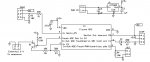
EDIT: In your second diagram, the PNP will be turned on anyway, if its emitter (i.e. batttery voltage) is more than about 5.6 volts (5v + Vbe). Also, Leg 4 of an 08M2 is NOT an ADC input!

Cheers, Alan.
 
Last edited:
also using the regulator may not work as the 7805 requires 2 volts more going in than coming out to function reliably 6volts is probably too close to the margins. You could probably use a couple of diodes in series to get the voltage drop you'd need for the Picaxe.
As eggdweather says using a transistor will not be of any benefit current wise.
Regards
Neil
The input to the regulator is from a 9V wall unit. The 6V that I want to monitor is from a separate source with a common ground.
 

eggdweather

Senior Member
I don't see where PWR is defined as 6v so not sure about the above comment. As long as it's above about 7v you should be OK.

I would try this...put two ordinary silicon e.g. 1N4001 diodes in series with the battery to be measured and feed it straight into the ADC. The diodes will stop the ADC voltage going above supply voltage.

Current drain into the ADC will be tiny - you could measure it withan accurate meter but it will be inconsequential.

You will have to take account of the volt drop across the diodes in the software to get the battery voltage from the ADC reading but that should be straightforward...but don't assume an ideal 0.6v across each diode for various reasons, do some measurements with your DMM and see what it actually is and use that value.
Yes, that will now work OK, it will now save power when the transistor is not on, not much but it will save a little.
 

AllyCat

Senior Member
Hi,

Diodes are not a "perfect" solution because they require some current to flow and their drop also varies somewhat with temperature. But they're probably "good enough".

However, if you really want a "zero drain" solution, then connect the base of a low-power NPN directly to Leg 4 and emitter to ground. Collector through a resistor to the base of a PNP transistor in the top end of the divider chain (tapping point goes to Leg 3). Then you can enable the voltage divider chain with PULLUP 8 and disable with PULLUP 0.

Cheers, Alan.
 

AllyCat

Senior Member
Hi,

A 10k + 50k divider may still go above the 5 volt Vdd rail. Exactly what ratio you choose depends if you plan to use the 7805 (Vdd) or the internal FVR (4v or 2v) as your "reference" voltage, but maybe 15k + 27k.

Personally I'd use a larger value resistor between the PICaxe and the NPN base. Even the internal 30k (nominal) Weak Pullup (on any pin) should be fine (perhaps with a higher, or no, base-emitter resistor, R9).

Cheers, Alan.
I plan to use the Vdd value as a reference (assumed to be 5.0V). And, per your suggestion, I will recalculate the ratio R6/R3 once I meassure the actual voltage from the batteries that I will be monitoring. Also I think I should replace the LM7805 with an LM317 so I will be able to make fine adjustments to Vdd.

Your input has been very helpful and I appreciate it. Thank you from an old (very old) Civil Engineer that 50 years too late decided to read the text book on electronic circuits that was ignored while in University.

Andrés
 
Last edited:

inglewoodpete

Senior Member
....Thank you from an old (very old) Civil Engineer that 50 years too late decided to read the text book on electronic circuits that was ignored while in University.

Andrés
Andrés, Good on you for keeping your brain cells ticking over at your esteemed age. I hope I'm able to keep doing something similar in just a few years time.

And I suspect that you actually had to buy a slightly more up-to-date text than the one that you (didn't) use in university!
 
New update.
  • Added an NPN transistor to switch on the PNP
  • Added 3 pin jumper to allow me to connect the emitter of the PNP to either Vdd (5V) or the external voltage that I want to measure.
  • Replaced the LM7805 with an LM317
  • Also, not shown in the schematic, I will replace the 50K R3 with a 100K trim pot to be able to adjust the output of the voltage deviver
Perez Counter SCH.jpg
 
Last edited:
Top