USB->Serial Support

thursdaybloom

New Member
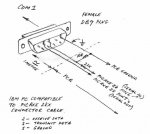
I have a USB->Serial cable at home already which I bought from Jaycar a while back. The part number on the packet is GUC-AD9 and the Jaycar part number is XC4834. I just wired up a 3-wire DB9 cable following the directions in the Manual Section 1.

I've set the cable up on COM5 before and it appears to be fine. When I try to download a program to my 08M it always fails. The Programming Editor brings up an error screen with a list of possible reasons why. None of them apply except maybe the 'unsupported USB->Serial adaptor'. How do I know if my cable that I have supports this 'breakout' command? When I run the 'test' via the Programming Editor and follow the instructions with testing voltage with my multimeter I always get -0.6V when the test LED is off [should get between 0V and -1V so this is fine]. When I click on the test LED the voltage moves to 4.1V, which I assume is a sufficient transition to high.

I was really hoping to get started on learning about Picaxes tonight but I just can't seem to be able to download the program

Can anyone help me at all? Much appreciated if you can

Cheers
 

ylp88

Senior Member
Try connecting the RX and TX and seeing if you can get a loopback working - send something using Terminal and see if you receive it back.

Otherwise I assume that you've double checked all your connections. Also make sure you have a nice, clean power supply.

ylp88
 

thursdaybloom

New Member
Thanks for the quick reply!

My knowledge of RS232 is my weakest field in computing I would say, and my background in coding is nil - hence the desire to get this picaxe up and running ASAP

As a result I'm not too sure what a loopback is nor do I know if you mean a Terminal within the editor or the command prompt. I apologise for my ignorance. I'm sure to hang my head in shame when I realise how dumb the question is and how simple your answer is
 

moxhamj

New Member
Not a dumb question at all! In fact, getting the serial cable working is probably the hardest bit of the picaxe equation. When it works, it works perfectly. When it fails, there are many reasons. We need to work through them all because once you get a chip programmed you will be hooked. And let's face it, we are all just picaxe pimps and pushers here!

Ok, first test. With nothing connected to the cable at all, can you look at the D9 male plug and read the tiny pin numbers (you might need a torch) and measure the volts between pin 5 (gnd) and pin 3. You should get -12V. If it is something different, then this may not be compatible with the standard 22k/10k download circuit.

After that, we can look at the USB installation in windows and check it actually installed.

Then, join pin 2 and 3 and try a loopback test with hyperterminal.

Then try downloading and measure the volts on pin 3 as it downloads.
 
Last edited:

slimplynth

Senior Member
Hi Thursday, did you get the 08m starter pack or just the 08m chip? when i've had this error its either because either...

the comport wasn't configured correctly (in PE..view>>>options>>>serial ports>> check that the comport is configured and the same as the one being used by the PE)

or my soldering was no good.

Attached is a pdf of the circuit i made for downloading to 08m, worked fine for me.

regards

slimplynth
 

Attachments

thursdaybloom

New Member
Thanks Dr Acula.

Voltage between pin 5 and pin 3 = 6.43V

My power supply is 3xAA which is outputting 4.6V


I found the 'Terminal' in the Programming Editor but don't know how to use it.
 

westaust55

Moderator
I note the Jaycar website also includes drivers for this USB to serial cable which I presume you have downloaded.

With the Rev Ed AXE027 USB to serial (non- RS232 voltages) it is essential to use the FTDI drivers from the Rev Ed website. I know it is also the case with the BASIC Stamp connecting cables.

My understanding is the standard Microsoft drivers will not work with the USB to serial cables for programming of the PICAXE chips.


If you start the Programming Editor without the cable connected (at least for AXE027) the Programming Editor "forgets the comm port assigned previously and it needs to be set again to the correct comm port.

These issues may be the same with the Jaycar cable as well.
 
Last edited:

moxhamj

New Member
Pin 5 and 3 should be negative volts. Can you just double check the polarity. Ground on the multimeter to pin 5 (and presuming ground really is ground - I have a multimeter where gnd is the +ve lead for some strange reason). pin 5 is the ground on the RS232 plug.

Presuming gnd is ground, 6.43V would be -6.43V and this may well be not low enough -9 to -12V would be better

Next test, if you can, is to try downloading a program with the multimeter on those pins. It should go from negative volts to positive. The download will fail but the important thing is that the volts change on the pin 3.
 
Last edited:

thursdaybloom

New Member
Slimplynth: I have checked the drivers are installed. They're on COM5 and I triplechecked that the PE was also set to COM5

Acula: Black multimeter lead on pin 5 + Red multimeter lead on pin 3 + Autoranging multimeter set to DCV = 6.43V


I think I figured out the 'Terminal' in the PE. I connected pin 2 to pin 3 [DB9] and then typed 'one' into the output buffer and 'one' appeared in the input buffer. I repeated with 'hello' and 'onehello' was read in to input buffer. I repeated again with 'please work' and now my Terminals sits with 'onehelloplease work' in the input buffer
 

thursdaybloom

New Member
westaust55: The cable comes with a driver CD for all windows platforms. When it detected new hardware I selected 'connect to the internet'. It found nothing and advised that if I had a driver CD to click 'back' and insert it - which I did and from there it automatically installed the driver.

Do you recommend downloading the drivers from the Jaycar website?
 

thursdaybloom

New Member
Acula: I don't know where the polarity confusion is coming from, but I wired my cable back up to my breadboard and put my multimeter to the corresponding wires before running a program and got -6.43V

The important thing is that when I ran a program it moved from -6.43V to 6.15V... before the program failed of course :)
 

moxhamj

New Member
Ok. It is just you said 6.43V in post 6 which I took to be positive.

If it is negative, fantastic. If you have an echo on hyperterminal, even better.

-6.43 to +6.15V is great - data is going through.

I just checked my pin 3 and it is -10.3V. That is a direct RS232 output from PC - not via a USB cable.

The proper RS232 specs defines -3 to -12V as the resting volts. Your volts would work fine into a RS232 receiver, eg a max232, and that could be a solution if you have one.

The 22k/10k download circuit picaxe uses is a bit of a fudge. It assumes -9 to -12V. Lots of others have tweaked the resistors so it works with lower voltages. But I'm not quite sure how much to tweak them, though it probably would involve lowering the values. But if you go too far, you will zap the chip.

The other solution people suggest is to buy the download converter from reved. It gives the proper voltage swing. But you probably want this working tonite!

If you are feeling keen, do you have a HC04 chip or similar? You could use the 10k/22k circuit and go into an HC04 then another HC04 and then drive a led. It ends up being a simple voltage converter - a poor man's max232. But it does work and it is cheaper than risking zapping picaxes. Then use the HC04 to drive a led and try a download and the led should flash. If not, try 10k/10k. Use two HC04s in series - each inverts the data so it ends up the same polarity. -6.43V should come out the other end of the two HC04s as 0V and +6V should come out as 5V. Assuming a 5V regulated supply to the HC04. LS04 probably will work too.
 
Last edited:

thursdaybloom

New Member
Acula thanks a million for your help. It's now 10:20pm and I think i've given up for the night. I could just buy the RevEd cable but that means $ and time. Aztronics may carry it but going into town can't happen until Friday so that also = money + time. I don't have either.

I was hoping to get it going tonight because I'm real keen to learn. I'll be back into it tomorrow night. By HC04 do you mean 74HC04? I don't have any lying around - I could get some tomorrow but I mainly keep excess of 74HC14 lying around.

And about the polarity confusion - I did write a positive figure because thats what I got. When I did the volt swing test for you it was initially a negative value. Obviously did something wrong, but not to worry.
 

moxhamj

New Member
74HC14 will be fine.

Resting volts on an RS232 which is a male plug coming out of a PC should be negative. Which should translate to 0V when resting when you put it through a couple of inverters. And +5V when active. So you can then add a led/1k resistor and the led should flash when you download.

Never give up. Keep going to 1am!!

I think fundamentally the problem is your level translater hasn't got a big enough voltage swing.

I also have a feeling that a search of the forum might turn up some suggestions for different resistor values which means you might not need the HC04 or HC14.
 
Last edited:

thursdaybloom

New Member
Haha I want to not get fired tomorrow so 1am seems out. Besides, the more tired I am the more I'll stuff something obvious. I'll get cracking tomorrow at about 7 Adelaide time.

So about this 'breakout' command thing that the PE comment on being a possible failure reason - does it look like this cable is going to do it? I just have to tweek the download circuit some more?
 

moxhamj

New Member
Something isn't right though. You said -.6V and 4.1V in the first post. I presume at the picaxe pin. But that is ok for low and high values.

Makes me wonder about a zapped picaxe. Or something else not wired right. Any chance of a photo?
 

thursdaybloom

New Member
Tomorrow I'll be prepared for debugging so there'll be photos abound. If you're on then I'll run whatever tests you want to and post results and photos. For now though, I sleep.

Thanks again for your help. Very much appreciated
 

tarzan

Senior Member
Just in case there was any confusion as to which pin connected where, here is a diagram that I pulled of the Internet. I don’t know who the author was.
 

Attachments

thursdaybloom

New Member
Thanks for the pic Tarzan - I used it to double-check my wiring and confirmed I'd done it correctly.

Acula: let me know if there's anything you want me to do to try get this thing working. I just got home from work - unfortunately on time to buy anything today so if extra/different components are needed I'll dive head first into my bits-box to see what I have
 
Top