usb power for picaxe

nick12ab

Senior Member
Welcome to the PICAXE Forum.

It is designed for Arduino and will need inversion on the data lines for use with PICAXE. Alternatively use a utility to invert the signals for PICAXE use. After that, it will power and program an 08M2 - the 08M2 should work with the 3.3V signals.
 

hitsware

Member
> Welcome to the PICAXE Forum.

Thanks !

> It is designed for Arduino and will need inversion on the data lines for use with PICAXE.

Which one is standard ?
Mr. Picaxe ought to make a similar cable !
Or does he have a way via some adaptor or ?
Seems an obvious way to go.
 

westaust55

Moderator
> It is designed for Arduino and will need inversion on the data lines for use with PICAXE.

Which one is standard ?
Both are standards.
PICAXE and BASIC Stamps use the iNverted serial comms with Tx, Rx and Gnd but do not need the RTS or CTS signals for programming.
full RS232 based serial equipment has inverted signals on the pins of the DB9 and/or DA25 connectors with a "1" identified typically by a negative voltage in the range -3 to -25 volts rather than 0 Volts.

other microcontrollers use the True signal.


Mr. Picaxe ought to make a similar cable !
why?
Rev Ed and most PICAXE users use either a dedicated battery or regulated 5V supply (sometimes down to 3.3 Volts now for newer chips)
If you are reliant on the PC to microcontroller cable for power, how do you take you project away from the PC?
 
Last edited:

inglewoodpete

Senior Member
If you are reliant on the PC to microcontroller cable for power, how do you take you project away from the PC?
You can get USB cables 5 metres long.....:)

I've been using PICAXEs for over 5 years now and have not wanted to power one from a PC. I've never developed a project that needs to remain connected to a PC, though.
 

Goeytex

Senior Member
Many Uc development platforms have the option for USB power. It's convenient when developing code and has little to nothing to do with whether or not a final project will remain connected to the PC. It has to do with ease of use while in the development stage. No dead / weak batteries or weedy power supplies causing trouble, & the convenience of a single cable to the Dev Board.

I'm with the OP. An adapter that also brings out USB V+ and even some of the other signals (RTS,DTR,CTS,DSR) can be quite useful at times.
 

hitsware

Member
> how do you take you project away from the PC?

I don't.
all I want to do is get audio out of the chip
(and an envelope trigger)
I want to run it off the PC like a crude
programmable sound card.
 

Captain Haddock

Senior Member
In which case why not mount it inside the pc case and use a spare hdd power supply, maybe put a programming socket in an expansion card blank plate for easy access.
I'm guessing a hdd needs a good smooth supply.
 

Pongo

Senior Member
You can get usb/serial cables which include the rsr232 converter chip very inexpensively on ebay that also bring out the 5 and/or 3.3 volts. Prolific or FTDI is a good chip. I used one in my last project, I think I paid about $2.50 for it, it output both voltages but of course it took a couple of weeks to arrive.
 

hitsware

Member
> Originally Posted by westaust55
> full RS232 based serial equipment
> and other microcontrollers use the
> True signal
> RS232 uses the inverted signal
> and can be used directly with
> PICAXE using just a resistor.
> It becomes true if you use a MAX232.

CLEAR as MUD :)

So if I invert tx and rx off of this :
https://www.sparkfun.com/products/9717
I'm good to go ?
 

IronJungle

Senior Member
I do you a USB connector to power my dev board, but... I don't power it from the PC/Mac. I use a USB hub that gets power from a wall wart. I make too many wiring errors during dev time to risk the USB PS on my PC/Mac.
 

Haku

Senior Member
There's nothing stopping you opening up the plastic on the USB connector of an AXE027 to solder in +5v & GND lines.

But if you're using it for tinkering with stuff on a breadboard the possibility of a short is always there. My Asus Eee's simply do a panic shutdown & switch completely off if it senses things aren't right (ie shorting) but how other computers behave I have no idea.

Old mobile phone chargers can make good power sources for Picaxing, just make sure the voltage is right.
 

Goeytex

Senior Member
So if I invert tx and rx off of this :
https://www.sparkfun.com/products/9717
I'm good to go ?
Yep.

Just download the FT_PROG utility from FTDI and flash the EEPROM on the FTDI
chip so that all of the I/Os are inverted.

I suggest using a 100 ohm series resistor between the Picaxe Serout Pin and the
RX pin on the adapter since the I/O level output of the Picaxe will be 5V and the
FTDI RX is expecting 3.3v.

It is up to you then not to do anything that will short out the Vbus +5v and potentially
damage the PC. I use a 200ma Fuse and a 1N4001 Diode on the Vbus +5v to provide
a bit of protection.
 

hitsware

Member
Yep.

Just download the FT_PROG utility from FTDI and flash the EEPROM on the FTDI
chip so that all of the I/Os are inverted.

I suggest using a 100 ohm series resistor between the Picaxe Serout Pin and the
RX pin on the adapter since the I/O level output of the Picaxe will be 5V and the
FTDI RX is expecting 3.3v.

It is up to you then not to do anything that will short out the Vbus +5v and potentially
damage the PC. I use a 200ma Fuse and a 1N4001 Diode on the Vbus +5v to provide
a bit of protection.
Thanks ! ...... I was thinking of an actual inverter chip.
Your way is much better. Do I still need the 10k and 22k
as if I had the regular programming cable ?
 

hitsware

Member
This cable is a poor choice as a substitute for the AXE027 cable. The reason for this is the AXE027 cable has pulldown resistors on TX & RX and this cable has pullup resistors on TX & RX.
Can you suggest a cable and or adaptor that will do what I want to do ?
(program picaxe and supply Vcc on same usb channel)
 

lbenson

Senior Member
So far, I find it easier to use separate devices--pl2303 db9 cable for programming, and cheap cp2101, ch340/341, or pl2303 usb module for power and serial communication--if there is the extra pin available on the picaxe. The usb would be plugged into a little linux device running openwrt or debian--NSLU2, WL-520gU, Dockstar, WR703N.

I'd be happy to see a no-fiddling usb module solution.
 

Pongo

Senior Member
So far, I find it easier to use separate devices--pl2303 db9 cable for programming, and cheap cp2101, ch340/341, or pl2303 usb module for power and serial communication--if there is the extra pin available on the picaxe. The usb would be plugged into a little linux device running openwrt or debian--NSLU2, WL-520gU, Dockstar, WR703N.

I'd be happy to see a no-fiddling usb module solution.
Why isn't the usb adaptor type that I linked in reply #10 a "no-fiddle" solution?
 

lbenson

Senior Member
>Why isn't the usb adaptor type that I linked in reply #10 a "no-fiddle" solution?

Perhaps it is. All other ttl serial that I have seen idles high, where picaxe programming requires "idle low". I had never seen the designation, "ttl Rs232"--perhaps that is what is is meant--ttl levels idling low. Is that your experience?
 

Goeytex

Senior Member
I'd be happy to see a no-fiddling usb module solution.
So would I.

I'll try to post schematics and plans for a "no fiddling" CP2012 based solution in a day or so.
I'm building it now using the "BAITE" CP2012 Adapter. Will be jumper selectable for either
3.3v or 5V power.
 

Goeytex

Senior Member
hitsware,

You cannot tell from looking at PL2303HX Datasheet whether or not a particular adapter inverts the data and /or supplies RS-232 voltage levels.

Prolific does not make adapters or cables. They only make the USB Bridge chips (PL2303) and generally only sell them to OEM's. The Prolific PL2303 chip does not provide for inverted TTL levels or for RS-232 voltage levels.

If a Prolific based adapter inverts the data or supplies RS232 Voltage levels it is because extra components are included on the adapter / cable by the manufacturer of the cable / adapter (which is NOT Prolific). I have never seen a Prolific based adapter that supplies Inverted TTL logic levels. If the data is inverted ( Idles Low), then it is almost always because a MAX232 type chip is added onto the adapter board , and the TX output level idles at -10 volts and is active at +10v.
 
Last edited:

Goeytex

Senior Member
Attached is a schematic diagram that shows how to power a breadboard with USB 5v from an inexpensive USB to TTL adapter. The adapter I used is a Dorji DAC03 that uses the CH340 Chipset. This setup works flawlessly.

A CP2102 Based adapter will also work, but CP2102's seem to have timing issues with the Picaxe firmware and occasionally produce a memory verification error at the very beginning of the download before the progress bar appears. This happens if (and only if) the program running in the Picaxe is sending serial data using sertxd or serout on the serout pin. Downloads work without fail if a hard reset is used. Just press the switch and start the download, then release the switch when the download starts.

I tried several Prolific PL2303 based USB to TTL adapters but they injected so much noise on the USB 5v that downloads failed about 80 percent of the time with memory verification errors at random locations. These may have fake / counterfeit Prolific chips on them or the boards may just be of a poor design.

Diagram Notes:

Q1 act as a normally closed solid state switch & supplies power to the breadboard. It is used as a reset when a hard reset may be necessary. A PFET might be a bit more efficient but the PNP works just fine. The reset circuit can be replaced with a toggle switch.

Q2 & Q3 can be replaced with 2N7000s FETS if you have them. It works fine as is.

Note that I did not include a fuse or reverse polarity protection. If you feel the need for these then certainly add them.

Goey
 

Attachments

hitsware

Member
Attached is a schematic diagram that shows how to power a breadboard with USB 5v from an inexpensive USB to TTL adapter. The adapter I used is a Dorji DAC03 that uses the CH340 Chipset. This setup works flawlessly.

A CP2102 Based adapter will also work, but CP2102's seem to have timing issues with the Picaxe firmware and occasionally produce a memory verification error at the very beginning of the download before the progress bar appears. This happens if (and only if) the program running in the Picaxe is sending serial data using sertxd or serout on the serout pin. Downloads work without fail if a hard reset is used. Just press the switch and start the download, then release the switch when the download starts.

I tried several Prolific PL2303 based USB to TTL adapters but they injected so much noise on the USB 5v that downloads failed about 80 percent of the time with memory verification errors at random locations. These may have fake / counterfeit Prolific chips on them or the boards may just be of a poor design.

Diagram Notes:

Q1 act as a normally closed solid state switch & supplies power to the breadboard. It is used as a reset when a hard reset may be necessary. A PFET might be a bit more efficient but the PNP works just fine. The reset circuit can be replaced with a toggle switch.

Q2 & Q3 can be replaced with 2N7000s FETS if you have them. It works fine as is.

Note that I did not include a fuse or reverse polarity protection. If you feel the need for these then certainly add them.

Goey
Thanks :) ..........
I wonder why PicAxe doesn't include the 5V on their programming cable ?
I notice Parallax also omits this (to me) obvious nice feature .
 

westaust55

Moderator
Thanks :) ..........
I wonder why PicAxe doesn't include the 5V on their programming cable ?
I notice Parallax also omits this (to me) obvious nice feature .
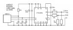
Consider the AXE027 cable.
It uses a standard 3.5mm stereo plug allowing the use of readily obtained stereo sockets for PCB or panel mounting.
By the nature of these plugs they have only 3 connections which allows for:
1. Tx
2. Rx
3. Ground
There is no spare connection available for +Vcc (as either +3.3V or +5V)

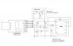
The earlier AXE026 programming lead was for connection from a PC serial DB9 connector.
The standard for the PC serial connectors for either 9 or 25 pin versions did not allow for the supply voltage to be made available on the connector, only ground and various signals.

The way some folks got around this for early PIC (not PICAXE) programmers and the like in the past, particularly with the 25 pin connectors, was to drive one or more of the unwanted signal pins to 0 giving a positive voltage due to signal inversion and using that as a source of power.

Had Rev Ed tried to bring out a +Vcc supply rail what connector would they choose as a standard?
It would need to be something that new comers to electronics can easily solder onto self assemble boards.
4 or 5 pin DIN? While readily available far more bulky.
USB connector? Compact but more fiddly to solder at home/school
 

westaust55

Moderator
> Were Rev Ed to bring out a +Vcc supply rail what connector would they choose as a standard?

Universal : http://www.mcmelectronics.com/product/83-14392

My personal thoughts to such a cable with 4 separate 1-pin headers is: it may be flexible/universal but, for beginners to electronics, No Way!

It would, as already suggested, need to be some form of 4 pin plug, but then what do those with existing Rev Ed and similar boards using a stereo plug and socket do? May be great in theory but not necessarily so in practice.

If one considers the number of newcomers to this forum who have problems with the basic two-resistor download circuit then having separate wires that can get mixed up (as is inevitable) will lead to more grief than advantage.

Rev Ed sell into the Education and the hobby markets. What they sell needs to involve systems that are well established, positive and helps to avoid problems.
 
Last edited:
Top