Trouble attaching LED + resistor to Picaxe-08 Proto Board - need help

redburns28

New Member
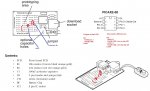
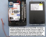
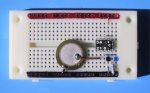
I'm currently trying to put together some Picaxe-08 Proto boards using the 08M2 chip. I'm having difficulty understanding where to place the LED and resistor on the board. I've seen the diagrams provided by the Picaxe website, but I guess I don't know how to read them correctly because my LEDs aren't working when I download the simple Flash program.

Any help on this issue would be greatly appreciated! Maybe anybody who has worked with these boards and has pictures of the final product?

Thanks
 

SAborn

Senior Member
You do realize that a led is a polorized component and only works one way, so you might have the led in circuit backwards, try turning the led around.
 

westaust55

Moderator
@Redburns

Firstly, welcome to the PICAXE forum.

Can you provide a link to the website for the exact proto-board that you have. In particular if it is not the Rev Ed AXE021. http://www.picaxe.com/docs/axe021.pdf
A link to where you found the circuit and program you are trying would be helpful.

The photos by afacuarius are not for the AXE021. Without the corresponding schematic they will not help greatly.

A photograph showing how you have connected the LEDs and post the program you have been tring may give us insights as to where you are going wrong and therefore make it easy for folks here to help you quickly.

EDIT: have you seen the circuit creator pages for an LED here:
http://www.picaxe.com/Circuit-Creator/Light-and-LCD-Outputs/LED/
 
Last edited:

redburns28

New Member

eclectic

Moderator
Here's the link of the product I've purchased - the P-AXE003U model. I purchased the LED and resistors separately from the kit.

http://www.wiltronics.com.au/catalogue/177763/picaxe-rf-dorji-robots-kits/picaxe/picaxe-08m2-starter-packs-and-project-boards

I don't have a picture with me at the moment, but I took out the original LED/resistor setup because it didn't work, but I can solder the parts back in again if need be.

Tx
"Original LED"?

Where did it come from?

And, please supply your "flash" program,
so that people can advise on the circuit.

e
 

westaust55

Moderator
Okay so you do in fact have the AXE021 PICAXE 08M(2) Proto board in that starter pack.

If you want to connect an LED and Resistor then see the attached image. For the resistor you can use 330 Ohms, 390 Ohms, 470 Ohms or even 510 Ohms without doing any damage.

One item you should bu,y if you do not already have one, is a solderless bread board into which you can insert components and wiring up circuit for experiments.
You can only carefully add and remove components on a soldered proto-board a few times and risk having the solder tracks lifting.
Better to solder some header pins or sockets (sockets best) into the first row (closest the PICAXE chip) of the 08M2 proto-board as a means of connecting wires from the proto-board to other circuits/boards.

On the attached image you will see two examples of program code that will flash an LED wires as per the diagram.
 

Attachments

Last edited:

manuka

Senior Member
Indeed welcome RedBurns28, & from Vanuatu no less! Just what are you doing in that fine country (which UK/EU/US readers are probably Googling to locate)- education or passing yacht ?

I totally agree with westaust85 re the benefits of breadboards. Perhaps the best PICAXE application resource is Andrew Hornblow's . I've used similar approaches since 2003, but am most recently guilty of slicing breadboards to fit into a partially gutted AA battery box, powering circuitry with a single 3.2V LiFePO4 cell.

Both Andrew & I highly recommend soldering final circuitry onto Kiwi Patch Boards (or slices). FWIW soldering should be the last thing you do, and at the stage when everything is tamed and understood.

Stan (in nearby New Zealand)
 

Attachments

Last edited:

redburns28

New Member
Thanks, this is exactly what I was in need of! The 'C' shape line on the left - is that the leg of the LED?

I'll try it out and hope that it works. Definitely going to get the breadboards for the next project... does seem a whole lot easier.
 

redburns28

New Member
Haha, I get that a lot. I'm actually from the states and nobody has a clue where I'm located. I am here teaching IT on one of the outer islands. It really is a great place to live, just hard to get things done sometimes.

Thanks for responding btw. Will try out the diagram from Westaust55 and hope for the best :)
 

westaust55

Moderator
Thanks, this is exactly what I was in need of! The 'C' shape line on the left - is that the leg of the LED?

I'll try it out and hope that it works. Definitely going to get the breadboards for the next project... does seem a whole lot easier.
The red "C" shaped line was/is intended to be a wire to connect the PCB track for the LED cathode to ground. Alternatively you could conenct the LED cathode directly to ground and reduce the number of soldered points.
 

sinav

New Member
@redburns28, so I’ve been trying to find these LEDs and I was wondering if I could get some pointers from you. I don’t have any hopes of finding the exact LEDs with a similar part number but I think I can safely place other LEDs on the picaxe-08 board provided I have matching specifications. If you have any address of a vendor from where I can get these shipped or the exact or even near exact specifications, can you please share them with me. I’m making this board for a friend of mine and I really don’t want him to have any issues later.
 

tony_g

Senior Member
@redburns28, so I’ve been trying to find these LEDs and I was wondering if I could get some pointers from you. I don’t have any hopes of finding the exact LEDs with a similar part number but I think I can safely place other LEDs on the picaxe-08 board provided I have matching specifications. If you have any address of a vendor from where I can get these shipped or the exact or even near exact specifications, can you please share them with me. I’m making this board for a friend of mine and I really don’t want him to have any issues later.

you can use any 3mm/5mm led (as long as they are not high power)and the mentioned resistors. ebay,digikey,maybe even the source will have some as well as any basic electronics shops you may have in town.

tony
 

westaust55

Moderator
@Sinav,

Welcome to the PICAXE forum.

As sugegsted by tony_g, you can use any LED with a current rating of less that 20 mA.
Typically newer high brighness LED's can produce ample illumination with as little as 5 or 6 mA current.
A higher value series resistor will reduce the current through the LED. Different LED colours have different forward volt drop values so the resistor can be adjusted to suit the current and brighness level.
PICAXE outputs are rated to 20 mA each but be aware that some chips have a maximum of 95 mA total for the chip.

@JimPerry,
if you are making comment (Welcome again) to redburns28 of Vanuatu, note that (s)he has not be on line for many months now.
Form Forum member "View Profile" ==> Last Activity: 24-09-2013 17:14
 
Last edited:

cilek

New Member
@redburns28, I think that basic electronic knowledge is still required before you try to put together a proto board, just as a concern for your own safety. However, since you’re just starting to experiment with it, I think you’d love to know about some exciting applications. For example, with voltage and current sensors integrated in different electrical boards or rooms of your house, you can monitor and control power of each room. You can have laser sensors communicating with the board and letting you know about the safety of your home and so on.

pcba manufacturer
 
Last edited:

westaust55

Moderator
@redburns28, I think that basic electronic knowledge is still required before you try to put together a proto board, just as a concern for your own safety. However, since you’re just starting to experiment with it, I think you’d love to know about some exciting applications. For example, with voltage and current sensors integrated in different electrical boards or rooms of your house, you can monitor and control power of each room. You can have laser sensors communicating with the board and letting you know about the safety of your home and so on.
Cilek,

Welcome to the PICAXE forum.


as for Redburns28, (s)he has not been active on the forum since that post 11 months ago.
Join Date: 11-09-2013.
Last Activity: 24-09-2013 17:14
 
Top