Totally Lost

marcos.placona

Senior Member
Hi, some people might have seen my post today about the seven segment displays. In fact, I decided to take the advices and move from it to a LCD display. The display I've got are the Dog Displays from MMS (http://www.mmselectronics.co.uk/lcddog.htm)

I know it should use just 4 wires to have the whole connection, but I can't really understand how to wire it up.

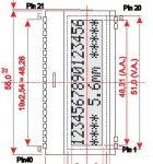
This is the display:


As you can see, it has 20 pins on the top, and four (two on each side) on the bottom.

I understand that I need to have those 4 pins on the bottom connected, as I'm not using any backlight, but have no idea about which pin is which on the top.

I got this from the datasheet, but honestly I didn't understand. Bear with me, I'm just a starter on this whole thing:


I'm not asking for anyone to do the job for me, I just want to have some guidance about where to go. I've read the manual about 10 times now to see if I could get something, but things don't make sense at all for me.

I have no idea about what those pins mean, so I don't know how to start to code this thing. I just wanted to display something like a "hello world", and would go from that to my application, but the way it stands now, I think I don't even know how to display it.

I've been doing reseacrh on it the whole day, but can't get anything working.

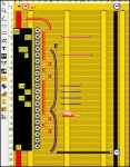
I even found this example by MELAZARUS (http://i15.tinypic.com/2uqeiic.jpg), and tried to wire it up the same way, but simply nothing happens.

Can someone please help me?

Thanks in advance,
 

Dippy

Moderator
Statement No.1. I've never heard of or used these displays before.
So, this is purley a guess.

Have you actually tried wiring up the display as though it were a 'traditional' 4 bit display?

That is what I would try to start with and proceed from there.

If running at 5V it looks like you Ground CSB and run it like a normal 4 bit.

After that you can fiddle with SPI.

I gotta ask: why did you buy one? (Price I assume??)
 

marcos.placona

Senior Member
Statement No.1. I've never heard of or used these displays before.
So, this is purley a guess.

Have you actually tried wiring up the display as though it were a 'traditional' 4 bit display?

That is what I would try to start with and proceed from there.

If running at 5V it looks like you Ground CSB and run it like a normal 4 bit.

After that you can fiddle with SPI.

I gotta ask: why did you buy one? (Price I assume??)
Bought the a long time ago after reading this thread:

http://www.picaxeforum.co.uk/showthread.php?t=6114&highlight=dog+display

They seemed to be easy to use, and the price was actually very good.

As per the four bit display, you mean something like this:


If so, I'll try something like that.

Is there any simple code I could run to see if this thing works or not?

Thanks
 

Dippy

Moderator
I would have thought there gallons of examples if you search the forum and I'm sure that hippy has some example stuff on his site but I don't know the address.

But yes try like a standard 4-bit like your image though obv you'll have to translate it to PICAXE i/o. And the contrast is s/w set according to Data Sheet.

Have a search.
 

moxhamj

New Member
Can you post your code? It will be a wiring problem or a code problem. Sometimes you need to go right back to basics and output the very first data nibble then put "end" after that and get a multimeter and test the actual voltage on each pin.
 

marcos.placona

Senior Member
Hi, thanks for all the answer, I'm gonna show here the way I wired the LCD. I followed Hippy's website to know which pins connect where, and also followed the schematics given by the the suppliers.

The schematic I followed:


The way I wired:


I'm just supposing that the 20 pins on the top go to the same way as the schematics they provide (i.e. VDD starts on the left and goes all the way to the last pin)

Still nothing happens, not even a blink, it gives no sign of life :confused:

Thanks for all the answers, and I hope someone can help me with that.

UPDATE: I think it's worth mentioning that I didn't include the picaxe connections on this diagram just to save some space, but I actually have it all well connected and working perfectly.
 
Last edited:

hippy

Ex-Staff (retired)
I'm just supposing that the 20 pins on the top go to the same way as the schematics they provide (i.e. VDD starts on the left and goes all the way to the last pin)
I think that's a bad assumption. To me it seems they have numbered the pins as if it were a 40-pin DIL. Thus pins 1-20 would run down the left, pins 21-40 run up the right.

If that's what you mean, your wiring doesn't match and it appears the voltage may have been inverted across the LCD which could have permanently damaged it.

Added : Page 8 of the DOG datasheet shows it is labelled as if it were a 40-pin DIL. Also note that CAP1N and CAP1P should be open-circuit when used at 5V.

http://www.lcd-module.de/eng/pdf/doma/dog-me.pdf

The moral is; always read the datasheet rather than make assumptions. All the required information is usually there and someone can usually be found to help interpret anything that isn't clear.
 

westaust55

Moderator
Totally Lost - LDC connection to PICAXE 18

As Hippy says,

As per your dwg/picture, pin 1 at top left, pin 20 at bottom left, pin 21 at botom right and pin 40 at top right.

Then as a starting point for Datalines (formatting likely will be bad here),
Bit__LCD_Pin__PICAXE18_Pin___Vdd_(+5V)
0_____35 ____________________Yes
1_____34_____________________Yes
2_____33_____________________Yes
3_____32 ____________________Yes
4_____31_______10
5_____30_______11
6_____29_______12
7_____28_______13

See attached extract from Datasheet for LCD pinout

Lots more that also needs fixing so as Hippy says, re-read the datasheets
 

Attachments

Last edited:

marcos.placona

Senior Member
Right, I think it make sense now. It's 1-20 on the bottom and 21-40 on the top.

I'm gonna try this way. Though I have to say that their drawings don't make sense at all as they have 26-27 then 21... it's so confusing.....

I'll see if I get to something doing it this way.

Thanks guys, I'll come back with some feedback.

Cheers
 

hippy

Ex-Staff (retired)
Functional diagrams are usually produced so the control lines are grouped in a way to make readable sense and the actual pin numbering can be all over the place in relation to that. It's just something one gets used to after a while.

Double check with the datasheet but I think your wiring ( excluding backlight if any ) should be like this ...

Code:
        .----------.
      --| 1     40 |-- 5V
      --| 2     39 |--------- RS
        |       38 |-- 0V
        |       37 |--------- R/W
        |       36 |--------- E
        |       35 |-- 5V
        |       34 |-- 5V
        |       33 |-- 5V
        |       32 |-- 5V
        |       31 |--------- D4
        |       30 |--------- D5
        |       29 |--------- D6
        |       28 |--------- D7
        |       27 |-- 0V
        |       26 |-- 5V
        |       25 |-- 5V
        |       24 |-- 5V
        |       23 |-- 5V
      --| 19    22 |--
      --| 20    21 |--
        `----------'
 

marcos.placona

Senior Member
Gotcha Hippy. And after I wire it like this, can I simply use the code examples from your website? The pins it'll connect will be the same.

UPD: Just updated my picture, and think it should be fine now. Hippy and westaust55 and the others, you rock :)

I shall put everything on the breadboard now and will come back with some feedback.

 
Last edited:

hippy

Ex-Staff (retired)
Yes, once wired that way - and take R/W to 0V - the LCD should work with both the Rev-Ed LCD code in the manual and my own code. Have a read ( I haven't ) of the previous link to using this type of display with a PICAXE as there may be things you do need to change.

You might need to connect the backlight if there is one but it is likely usable without even if not easy to read.

The problem you'll face if it doesn't work is that you won't know if you've destroyed the LCD already or if it's a problem of wiring or in software. The best I can suggest is try it and see what happens, and we can take it from there. Fingers crossed and the LCD will have survived.
 

marcos.placona

Senior Member
Right, so I've rewired everything in the way you advised me, but still nothing. No lights, no nothing. Nothing happens at all.

I tried the manual's software and Hippy's, but no one worked.

Any other suggestions?

Ahh I've also tried a second piece of the same LCD I've got here, but nothing happens to this one also.

Cheers
 

eclectic

Moderator
Marcos.

Can you provide an EXACT circuit, and a photograph?

EVERYTHING that is on the board.

If you are using LochMaster, then change the colours of the wires,
so that it is easier to see.

I can send an example, if you need one.

e.
 

hippy

Ex-Staff (retired)
Also make sure you have your circuit diagram / layout right and that what you build matches the layout ... for example, where does the wire from pin 27 go ? Not to 0V; it misses that by one track.
 

moxhamj

New Member
We can get this working but we need more information. Can you please post all the code (just copy and paste it), the latest wiring diagram and a digital photos of both sides of the board.
 

marcos.placona

Senior Member
Hi, I'm sorry for the delay in answering this, but here we go.

First, I've made the changes with the colours on the wires and everything, so it's easier to see which wire goes where, and have also added a legend, so you now which colours does what.


cute isn't it? :D

Here's the link for the *.rst file, so those who have lochmaster can take a look at it, but I've made sure everything is well connected and isolated.

Link: lcd_wired.rst

The code, is the same used by Hippy on his website. I reckon it could not work exactly the same way, as I'm using a different device, but I believe it would at least give a sign of life or whatever (didn't happen anyway).

Code:
[COLOR=black][COLOR=black]SYMBOL  RS        = 2         ; 0 = Command   1 = Data
        SYMBOL  E         = 3         ; 0 = Idle      1 = Active
        SYMBOL  DB4       = 4         ; LCD Data Line 4
        SYMBOL  DB5       = 5         ; LCD Data Line 5
        SYMBOL  DB6       = 6         ; LCD Data Line 6
        SYMBOL  DB7       = 7         ; LCD Data Line 7

        SYMBOL  RSCMDmask = %00000000 ; Select Command register
        SYMBOL  RSDATmask = %00000100 ; Select Data register

        SYMBOL  get       = b11
        SYMBOL  byte      = b12
        SYMBOL  rsbit     = b13

    PowerOnReset:

        GOSUB InitialiseLcd

    DisplayTopLine:

        EEPROM 6,("Hello")

        FOR get = 6 TO 10
          READ get,byte
          GOSUB SendDataByte
        NEXT

    MoveCursorToStartOfSecondLine:

        byte = $C0
        GOSUB SendCmdByte

    DisplayBottomLine:

        EEPROM 11,("World!")

        FOR get = 11 TO 16
          READ get,byte
          GOSUB SendDataByte
        NEXT

        END

    InitialiseLcd:

        FOR get = 0 TO 5
          READ get,byte
          GOSUB SendInitCmdByte
        NEXT

        ' Nibble commands - To initialise 4-bit mode

        EEPROM 0,( $33 )    ; %0011---- %0011----   8-bit / 8-bit
        EEPROM 1,( $32 )    ; %0011---- %0010----   8-bit / 4-bit

        ' Byte commands - To configure the LCD

        EEPROM 2,( $28 )    ; %00101000 %001LNF00   Display Format
        EEPROM 3,( $0C )    ; %00001100 %00001DCB   Display On
        EEPROM 4,( $06 )    ; %00000110 %000001IS   Cursor Move

                            ; L : 0 = 4-bit Mode    1 = 8-bit Mode
                            ; N : 0 = 1 Line        1 = 2 Lines
                            ; F : 0 = 5x7 Pixels    1 = N/A
                            ; D : 0 = Display Off   1 = Display On
                            ; C : 0 = Cursor Off    1 = Cursor On
                            ; B : 0 = Cursor Steady 1 = Cursor Flash
                            ; I : 0 = Dec Cursor    1 = Inc Cursor
                            ; S : 0 = Cursor Move   1 = Display Shift

        EEPROM 5,( $01 )    ; Clear Screen

        RETURN

    SendInitCmdByte:

        PAUSE 15                        ; Delay 15mS

    SendCmdByte:

        rsbit = RSCMDmask               ; Send to Command register

    SendDataByte:

        pins = byte & %11110000 | rsbit ; Put MSB out first
        PULSOUT E,1                     ; Give a 10uS pulse on E
        pins = byte * %00010000 | rsbit ; Put LSB out second
        PULSOUT E,1                     ; Give a 10uS pulse on E

        rsbit = RSDATmask               ; Send to Data register next

        RETURN
[/COLOR][/COLOR]
I've also tried to use the one from the manual three, but also, no luck.

As per the pictures requested, I'm gonna ask my wife to take a picture of it (currently on the breadboard, but with the exact same wiring).

Well, I wanna thank you guys for being so helpful, I'm really happy I can count on you, and I promise to write a nice tutorial about this in the future so other people don't go though the same "pain" I'm going now.

I shall pay some pints of lager (for the guys in UK) when I come over :p

Thanks in advance,
 

westaust55

Moderator
Marcos,

Tried to put this thread/question up this morning but the forum as far too slow and had to head of to a training course.

Have you installed any wiring for the power +5V and 0V to the PICAXE?
Your diagrams do not show this.
 

eclectic

Moderator
Marcos.
In your circuit, I'm assuming that the Picaxe section is working,
with the fixes mentioned by Dr A and Westaus.
Have you also go all unused inputs connected to gnd?
AND, a 100nF capacitor?

Some other points.

1.Mycroft's post mentioned the delay needed to initialise.
In the link he posted, it mentions switching on the LCD BEFORE the Picaxe.

2.In the link, and in the datasheet, it mentions a 100nF capacitor,
between LCD pins 26-27.

In future projects, it might be useful for you to make a “breadboard” layout
in Lochmaster. Check it first, with the continuity tool, and then it could be helpful
when wiring.

e.
 

Attachments

manuka

Senior Member
Ah that's more like it! Straight Vero layouts can rapidly turn "swampy", as witnessed by this little beauty. Dippy will no doubt think it's one of my pre breadboard efforts-


How have folks found Lochmaster by the way? (Scotties relax-"Loch" is German for "hole" of course)
 
Last edited:

moxhamj

New Member
Re my previous comment, I note an earlier comment that the picaxe is wired up correctly even though not shown. I presume you can put in some simple code 'high 7' etc and test the pins do indeed go high at the display (just thinking of dry joints and the like). I haven't double double checked the 4 data pins are in the right order - maybe some kind soul can go back to the original datasheet on the first page of this thread and compare with a 16x2 lcd pinout. The other pins do seem correct. Photos would be helpful when you can get them :)
 
Last edited:

westaust55

Moderator
LCD conenctions - data signals

I haven't double double checked the 4 data pins are in the right order - maybe some kind soul can go back to the original datasheet on the first page of this thread and compare with a 16x2 lcd pinout.
Yes the data connections for the high nybble are correct.
The schematic Marcos has at Thread 1 is from the datasheet (and I checked before). Myself at thread 11 (corrected table) and Hippy at thread 13 also reflect the correct connections for data.
 

marcos.placona

Senior Member
Hi, it is indeed connect to the picaxe, and the picaxe download circuit works well, it's just not wired up on the image I sent to save some space, and to not complicate things more, as I found that it was going beyond imagination with all those wires. I used a voltmeter to test that everything was going to the right places, including that the pins were really going high and low.

As for the questions asked:

1.Mycroft's post mentioned the delay needed to initialise.
In the link he posted, it mentions switching on the LCD BEFORE the Picaxe.

So this can be done by just powering up the LCD before I even power up the picaxe right?

2.In the link, and in the datasheet, it mentions a 100nF capacitor,
between LCD pins 26-27.

Will add this to my project, and see what it does.

Regarding the pictures, I'll post them here tonight as I'm in the office right now.
 

moxhamj

New Member
Re delays and switching the display on before the picaxe, I just put a pause 1000 at the beginning of the code. The picaxe will power up with all the pins low, and a second for the display to stabilise should be fine.

I am still trying to double check the 4 data wires are correct. My brain hurts coz I've been at work for the last 14 hours, but the very first nibble of data that goes out is 0011 and that should make DB4 high, DB 5 high, DB 6 low and DB 7 low.
 
Last edited:

marcos.placona

Senior Member
Re delays and switching the display on before the picaxe, I just put a pause 1000 at the beginning of the code. The picaxe will power up with all the pins low, and a second for the display to stabilise should be fine.
Will try that then. This LCD display will be put in a photo frame once it works :D
 

moxhamj

New Member
First nibble thus will make pin 30 and 31 on your display high. I wonder if you could just test that with an "end" after the first nibble goes out eg
pins = byte & %11110000 | rsbit ; Put MSB out first
end ; put this in temporarily
 
Last edited:

hippy

Ex-Staff (retired)
Reading the manual it may also be necessary to change the initialisation sequence, especially as contrast appears to be set entirely by software.

I'm assuming you have cut the tracks between pin 1 and 40 of the LCD etc.

The way I'd approach getting an LCD like this working is to get the PICAXE working with a genuine HD44780 LCD then wire the new LCD up the same way and see if it works. If not, study the manual, scour Google and every example program I could find and set myself down for a long and tedious process of trial and error. If still no joy I'd find a project which is known to work and replicate that exactly, or simply give up on it.

Make sure you are using the LCD which is least likely to have been damaged. If the LCD is damaged it's going to be a long and frustrating haul to get absolutely nowhere.

My best advice for people who aren't familiar with LCD's and don't relish the frustrations of trying to make an 'unknown' work is to stick with genuine HD44870's or others which have been proven to work with a PICAXE. This is one of the cases where 'cost savings' can turn out to be no such thing.
 

marcos.placona

Senior Member
Hi guys it's me again, I've just tried everything you've mentioned, but nothing really changed anything.

I was doing some research on the ST7036 and found this:


If you see, all the red part if for the DOGM-LCD. Now I'm confused, it's again something else, and doesn't make much sense.

What do you guys think?

Cheers
 

eclectic

Moderator
Marcos.

I think it's time to stop! Cut your losses.

Read what Hippy said in post #32. Perfect.

Can I just add one thing.
Buy an AXE033. Assemble it VERY carefully.
Then you can have a project that will work first time.

e.
 

marcos.placona

Senior Member
Marcos.

I think it's time to stop! Cut your losses.

Read what Hippy said in post #32. Perfect.

Can I just add one thing.
Buy an AXE033. Assemble it VERY carefully.
Then you can have a project that will work first time.

e.
RIght, but I don't give up so easily. I've just sent an email to the manufacturer asking for his help. I shall come up with something working in some days.

Let's hope :)

Cheers
 

hippy

Ex-Staff (retired)
If you see, all the red part if for the DOGM-LCD. Now I'm confused, it's again something else, and doesn't make much sense.
The red part matches with the diagram in the datasheet and the layout you are using. Names are the same, pin numbers are the same. It simply confirms what we've already worked out.

Other coloured parts are for other devices so can simply be ignored as you're not interested in those.
 

westaust55

Moderator
From your latest diagram (a little difficult to read - maybe the hour here), seems like pins 1 & 2 plus 19 and 20 could be for a backlight if fitted. They are seemingly labelled LED+ and LED- for each pair.
You have them bridged together.
If no backlight for your LCD module not a problem.
Otherwise not clear where they get power from and your wiring might be suspect for that part. Otherwise nothing else is obvious.
 
Last edited:

marcos.placona

Senior Member
Hi guys, just though it'd be good to update this thread. I finally got in touch with their sales manager, and he came up with a piece of code. I sent him my schematics and he said it's all connected properly (One thing less to be concerned).

Unfortunately, they don't have any code examples in Basic, but have this one in C. I'm not much of a C guy, but as far as I could understand, I'm not very far from what the code is doing. Here's what they sent me:

Code:
;Lcd       EA-DOG163
;Source    Unknown
;--------------------


#include <stdio.h>
#include <pic.h>
 

#define bitset(var, bit) ((var) |= 1 << (bit))
#define bitclr(var, bit) ((var) &= ~(1 << (bit)))


#define LED_PIN 5
#define LCD_CLK 3
#define LCD_DO 2
#define LCD_RS 4
#define LCD_CS 1
 
void DataLCD(unsigned char data_out);
void outLCD(unsigned char data_out);
void delay(char d);
 
void main(void)
{
 unsigned int i,j;
  
 INTCON = 0; // disable interrupts
 
 CMCON = 0x7;
 TRISB = ~(1 << LED_PIN); // configure all pins as inputs, except the LED_PIN
 TRISA = 0;
 

 bitset(PORTA,LCD_CS);
 bitclr(PORTA,LCD_RS);
 bitset(PORTB, LED_PIN); // turn the LED on
 
 delay(200);


  bitclr(PORTA,LCD_CS);
  outLCD(0x38);
  bitset(PORTA,LCD_CS);
  delay(255);				//Delay > 26.3uS
 
  bitclr(PORTA,LCD_CS);
  outLCD(0x39);				//DOGM163 @ 3.3V
  bitset(PORTA,LCD_CS);
  delay(1);
 
  bitclr(PORTA,LCD_CS);
  outLCD(0x15);
  bitset(PORTA,LCD_CS);
  delay(1);
 
  bitclr(PORTA,LCD_CS);//boost and contrast
  outLCD(0x55);
  bitset(PORTA,LCD_CS);
  delay(1);
 
  bitclr(PORTA,LCD_CS);// follower control
  outLCD(0x6e);
  bitset(PORTA,LCD_CS);
  delay(1);
 
  bitclr(PORTA,LCD_CS); // contrast
  outLCD(0x72);
  bitset(PORTA,LCD_CS);
  delay(1);
 
  bitclr(PORTA,LCD_CS); // display in off
  outLCD(0x0f);
  bitset(PORTA,LCD_CS);
  delay(1);
 
  bitclr(PORTA,LCD_CS); //clear display
  outLCD(0x01);
  bitset(PORTA,LCD_CS);
  delay(1);
 
  bitclr(PORTA,LCD_CS);// entry mode
  outLCD(0x06);
  bitset(PORTA,LCD_CS);


  bitclr(PORTA,LCD_CS); //write data
  DataLCD('B');
  bitset(PORTA,LCD_CS);
 
 bitclr(PORTA,LCD_CS);
  DataLCD('B');
  bitset(PORTA,LCD_CS);
 
 bitclr(PORTA,LCD_CS);
  DataLCD('B');
  bitset(PORTA,LCD_CS);
 
 
  while(1){;}
 
 
  while(1){;}
 

}
void DataLCD(unsigned char data_out)
 {
 unsigned char i;
 bitset(PORTA,LCD_RS);
 
 for(i = 0; i < 8 ; i++)  // For all bits of data
  { 
 
 
      // clock out data
  delay(1);
  if(data_out & 0x80)  // if bit 7 (MSB) of data set
   {
   bitset(PORTA,LCD_DO);   // set data pin high
   }
  else
   {
   bitclr(PORTA,LCD_DO);   // else set low
   }
  bitset(PORTA,LCD_CLK);
 
      // clock out data
  delay(10);
  bitclr(PORTA,LCD_CLK);
  delay(10);
  data_out <<=1;   // get next bit into bit 7// 
  }
  bitclr(PORTA,LCD_RS);
 }
 
void outLCD(unsigned char data_out)
 {
 unsigned char i;
 for(i = 0; i < 8 ; i++)  // For all bits of data
  { 
 
 
      // clock out data
  delay(1);
  if(data_out & 0x80)  // if bit 7 (MSB) of data set
   {
   bitset(PORTA,LCD_DO);   // set data pin high
   }
  else
   {
   bitclr(PORTA,LCD_DO);   // else set low
   }
  bitset(PORTA,LCD_CLK);
      // clock out data
  delay(1);
  bitclr(PORTA,LCD_CLK);
  delay(1);
  data_out <<=1;   // get next bit into bit 7// 
  }
 }
void delay(unsigned char d)
 {
 unsigned int i,h;
 for(h=0;h<d;h++){
  for(i = 0; i < 428; ++i){;}
 }
}
My question is:

Is there any C guru in here who could help me to translate this code from C to Basic (picaxe)?

Cheers
 

hippy

Ex-Staff (retired)
The code is simple bit-banging so shouldn't be too hard to translate even without a lot of knowledge in C but I'll be willing to translate it for you.

The code is for using the display in SPI mode so you'll have to ensure it is wired up for that mode. If it is already, that could explain why the 4-bit mode hasn't worked !
 
Top