The Pulsin command takes too much time - in search of ideas

Scheibuman

Member
Hello everyone,
My name is Dirk, I'm 50 years old, I'm from Germany and I'm new to the forum.
I have been looking for some time for a solution to program microcontrollers that I can understand in order to implement a few small ideas.
After some research I came across Matrix - Flowcode, but I found it too complicated. Then I came across Pixace, which I found very appealing because of BASIC.

In this very good forum I found a lot of code snippets to realize my current project, but unfortunately I encountered timing problems.


About my project:
I would like to have a motor extend and retract a component by reversing the polarity. The motor should extend for x seconds when the exit button is pressed briefly, but stop immediately when it is pressed again, i.e. interrupt the time loop. If you press the other button during the x seconds, the motor should retract for x seconds.
The same applies to the exit button.

However, the motor should also extend when a certain frequency is reached and retract again when the frequency falls below a certain level.
The frequency range is 0 to a maximum of 250 Hz, whereby the motor should always extend above 155 Hz, i.e. frequencies above 155 Hz are not important for me.
So let's just assume that the motor should extend at 120 Hz and retract at 20 Hz.

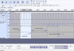
To evaluate the frequency, I wanted to use the Pulsin command. But this simply takes too much time. At 4Mhz and "open loop" programming, my program needs approx. 3 seconds for 255 runs without the Pulsin command. To measure this, I let an LED toggle in the Do-Loop instruction after 255 passes.
If I include the Pulsin command in the loop, the program needs 2:52 minutes(!) for the 255 runs at 0 Hz. At 10 Hz a good 25 seconds and at 120 Hz around 3 seconds again.
My problem is that the motor should only run for x seconds. I have to define a time somehow. At 0 Hz, however, the program always needs at least 0.8 seconds to run through once, and it gets faster at higher frequencies. The internal timer does not adhere to the specified time as soon as no frequency is present.

I have chosen a 14M2+ as µC, as I need 3 inputs and 3 outputs.
Running it at 16 or even 32 Mhz does not bring any noticeable time advantage, as Pulsin still needs the same time to determine the time between the edges.

Is it possible to limit the Pulsin command with a TimeOut parameter? Because it would be enough for me if it only fills the variable from 15 Hz and does not measure frequencies below that.

I am attaching the code I hope you don't stone me because of my bad English and the bad code (I don't know what is worse).


Code:
'Simple Flap
'Take2

Start:
setfreq m4 'Pimp my Pulsein 32 Mhz don't work...

'Labeling

'Inputs
    symbol inSpeed = C.0
    symbol inSWout = pinC.1
    symbol inSWin = pinC.2

'Outputs
    symbol outMotorUp = B.2
    symbol MotorUp = pinB.2
    symbol outMotorDown = B.3
    symbol MotorDown = pinB.3
    symbol outBeeper = B.4

'Buttondetection
    symbol SWoutTemp = b0
    symbol SWoutMem = b1
    symbol SWoutL2H = b2

    symbol SWinTemp = b3
    symbol SWinMem = b4
    symbol SWinL2H = b5

'Constants
    symbol conMotorOnTime = b8
    symbol conMotorOnLoop = b10

'Variables
    symbol vSpeed = b9
    symbol vTime = b6
    symbol LoopTime = b11

'Setting Constants
    conMotorOnTime = 6 '(3 sec at 32Mhz)

'Declare the outputs
    output outMotorUp, outMotorDown, outBeeper

'set outputs to low
    low outMotorUp
    low outMotorDown
    low outBeeper

'#terminal 4800


Main:
do    ' Detect pressed buttons (low->high)
      SWoutTemp = inSWout 'Copy Out-Switch-State to temp
      SWoutL2H = SWoutTemp andnot SWoutMem 'Compare Temp with Mem to Detect Button state
      SWoutMem = SWoutTemp 'write Temp to Mem

    SWinTemp = inSWin
      SWinL2H = SWinTemp andnot SWinMem
      SWinMem = SWinTemp
    
    LoopTime = LoopTime Max 254 + 1 'Counts the loops
    
      ' If low to high (L2H) is detected, select direction and start or stop motor
      if SWoutL2H = 1 then
        pinB.1 = 0 'Program time indicator
        MotorDown = 0 'Stop Motor Down, because motor can not up und down at the same time
            MotorUp = not MotorUp 'Toggle MotorUp
        let vTime = Time + conMotorOnTime
        elseif SWinL2H = 1 then '
        MotorUp = 0 'Stop Motor Up, because motor can not up und down at the same time
        MotorDown = not MotorDown 'Toggle MotorDown
        let vTime = Time + conMotorOnTime
        endif
'sertxd ("SWoutTemp: ",#SWoutTemp)
      
      if Time => vTime then 'Check Time if Time goes by:
        low outMotorUp ' Stop both MotorOuts
        MotorDown = 0
        Low outMotorDown
        MotorUp = 0
        vTime = 0
    endif
      if LoopTime = 255 then 'Programm has looped 255 times
        toggle B.1 'light up or down red LED
        LoopTime=0 'Reset LoopCounter
    endif
    pulsin inSpeed,1,vSpeed 'Check actual speed and slow down the code...
    

loop
 

Aries

New Member
Have you considered using the COUNT command instead? It can count the number of pulses in a short space of time (particularly if you use a higher frequency for the Picaxe (e.g. m16 or m32). I have used it with a Picaxe 20x2 to count the pulses from a flow meter.
 

Scheibuman

Member
Thank you very much for your support.
I have used the count command in another project. But this also has the disadvantage that the program stands for the time of counting. During the time in which the count command counts, the two buttons are not queried, for example. In order to record the 15 Hz reasonably accurately, at least 250ms would have to be counted. That would then be 3.75 pulses * 4 here the count command would count 3 to 4 (12 or 16) pulses.
A higher frequency does not lead to a higher resolution, as the frequency is specified externally and the count command always counts exactly the same time. If the frequency of the signal to be measured were higher in the kHz range, for example, a count with 50ms would be sufficient in terms of accuracy.
The Pulsin command is normally faster here, as only the time between 2 edges is measured and the frequency is calculated from this.
If nothing helps, I have to convert the frequency into a voltage (LM2907) and evaluate the voltage at the analog input of the Picaxe.
 

AllyCat

Senior Member
Hi,

Welcome to the forum. Actually, an 08M2 has 3 inputs and 3 outputs, or 2 x08M2 will fit in a 16-pin socket for true multi-tasking (two cores), but you are correct that a single 14M2 is probably the most suitable PICaxe to use here. :)

Note that many of PICaxe's timing parameters change with SETFREQ and in particular, PULSIN will timeout in about 82 ms ( 655 / 8) at SETFREQ M32. However, PICaxe's Interrupt facility may offer the best solution, even thought it is strictly a "polled" architecture. Maybe you could use the interrupts for your "button" inputs, or you might set up a timed interrupt (link) from a PWM output or a "Servo" pulse output.

Obviously a "zero" (or very low) frequency may cause problems with PULSIN (if the native timeout is too long for you) so you could poll the frequency input directly with a program code loop, or by an interrupt. If 15 Hz is your lowest frequency of interest then you can check if the input changes within a 66 ms period (or 33 ms if it is a 50% duty cycle square wave). Also the PEEKSFR and POKESFR commands allow access to many hardware features of the "base" PIC chips that are not supported directly by the PICaxe Basic Interpreter. For example the "Interrupt on change flags" are (In My Opinion) more useful than the "S-R Latch", and "Timer 1" [edit] is (usually) counting through 20 ms cycles (but unfortunately there is no access to the "prescaler" which divides these pulses (by 50) down to the 1 second "time" variable). The on-chip hardware Comparator(s) are also available on ALL present PICaxes. ;)

Cheers, Alan.
 
Last edited:

hippy

Technical Support
Staff member
If I include the Pulsin command in the loop, the program needs 2:52 minutes(!) for the 255 runs at 0 Hz. At 10 Hz a good 25 seconds and at 120 Hz around 3 seconds again.
Why do you need multiple PULSIN to determine the frequency ? Just one should give a pretty good indication of what the input frequency is.
 

erco

Senior Member
You could add external hardware to create a frequency to voltage converter, then read that quickly using a picaxe ADC pin. There are dedicated freq/volt chips or you can make one using a classic 555 timer.
 

Scheibuman

Member
Many thanks to all of you for the friendly welcome and your help here in the forum.

@AllyCat
Yes, I actually briefly thought about working with a 2nd CPU. But no, I think it has to work like this.
Is there perhaps an example code here in the forum where a servo pulseout can be used internally as an additional timer? That sounds very interesting.
The interrupts are also interesting. I had rejected the idea because I assumed that I could only assign an interrupt to one input and that I would need 2 buttons.
I'll have to read the manual and the forum again to find out how I can implement this.

@hippy
I need constant monitoring of the frequency. This is a speed signal from a rc-car, which should extend and retract a spoiler at a certain speed.
But you have given me food for thought. :D
I could query the input in the open loop and query the pulsin in a Gosub loop when 3 counters are exceeded. That would at least prevent the long timeout. That's easy for me to realise. I'll try it out straight away. Thanks!

@erco

I have already thought about this in my 2nd contribution in the last line. I would have used an LM2907 here. I used it years ago in a tachometer project (without a microcontroller). It is very easy to use.
But it's cool that this idea has been confirmed again. I suspect the interperter will only need a few ms for a readadc.

EDIT:

I noticed something else...
Could it be that while Pulsin is checking the input, the global timer variable is no longer counted? If I evaluate below 80Hz (50% spread), the motor-on time increases to over 3 seconds at 32Mhz pic frequency. At 15 Hz, the timer actually needs 20 seconds for 3 increments.
 
Last edited:

piclt

Member
......... pulsin inSpeed,1,vSpeed 'Check actual speed and slow down the code...

you are using the above line of code to measure the time between pulses received on pin inSpeed and storing it in vSpeed variable.

What are you doing with the value stored in vSpeed ??. I cannot see it anywhere else in your code.

The value of vSpeed lets you know when to extend the spoiler...??

If you forget about the rest of the code can you get pulsein bit on its own to give sensible values in vSpeed. It may be looping too fast and the value changing so quickly that you are unable to read it...???
 
Last edited:

AllyCat

Senior Member
Hi,

I haven't examined your code in detail, and for now just a few quick answers, because I am currently "traveling".

It's usually hippy who recommends using two (PICaxe) chips in multi-tasking type applications, where I normally like to (try to) do it with one. :)

Most of the "Port C" pins can be used as interrupt inputs, with various logic relationships supported for multiple inputs (see the SETINT command). But only one interrupt vector (program address/label) is available, so the interrupt routine itself must detect which pin(s) was activated. For a timer interrupt (with M2 chips) the simple method is to connect an external link between a pulse output pin (PWM or Servo) and an interrupt input pin (but other methods might be found to work).

Also, there are methods to apply more than one input (e.g. buttons pressed) to a single input, for example using an ADC input. ADC conversion takes less than 1 ms, but I believe the speed doesn't change with the SETFREQ command.

You haven't described the nature of your "frequency" waveform, but ideally it will be a square wave (50% duty cycle) or a narrow pulse logic waveform to measure the "absolute" frequency when using PULSIN .. , .. , period (e.g. Frequency in Hz = 50,000 / period , if a 50% duty cycle and SETFREQ M4 ). If you have a more irregular pulse train (or to detect if a pulse has "gone away") you might find the "Interrupt on Change Flags" or the "Timer 1 Gate" hardware is useful, as I have described in my link in post #2 of THIS THREAD.

Cheers, Alan.
 

Scheibuman

Member
@picit
The entire program is still under development. At the top, it says in the remark "Take2"; there's already a working Take1 and a completed circuit board (cutout in the profile picture) with a 14M2 as SIOC. However, there are always timing issues when querying the buttons. So, I've read a lot here in the forum and started the program completely new in an open-loop style.

In Take 2, I started with querying the buttons and then added holding the outputs for 6 seconds after pressing a button, changing the direction of rotation after pressing the other button, and stopping when pressing the same button again. I output variables to the terminal for visualization to see what's happening.

After adding Pulsin, the program became slow. However, the program must still work even when the vehicle is parking, so even at 0 Hz.

The evaluation of vSpeed is still pending, here in this case directly below Pulsin.

Setting the variable with the speeds at which the extension or retraction should be triggered is also still missing (setup menu). But this doesn't happen in the main loop. I do it step by step.

The biggest problem at the moment is that the running time of 6 seconds can no longer be realised. As the motor has its own end position detection, this is not time-critical, so it doesn't really matter whether it takes 6 or 8 seconds, but 15 to 20 seconds is still very long.

@AllyCat
I experimented with the servo command on PinC.5. I don't think I need an external connection to an input pin because I can directly query the pulses at PinC.5 in the program; at least it fills the variable. :)
The signal is, as you suspect, a 5V square wave with a 50% duty cycle. Here on my workbench, the signal is generated very cleanly with a function generator. On the vehicle, small edges can be seen at the ends with the oscilloscope, but no "losses." So, when the voltage rises, it overshoots to about 4.9 V and then runs cleanly with 4.75 volts. Therefore, the Pulsin had no problems in my first try in the car.

Thank you for your link. I'll take a closer look at that too. I don't expect you to work out everything for me; I'm very happy with hints like these. It gives you new ideas. Thanks again to everyone for the quick and numerous responses.
 

piclt

Member
you should check out the pulsin bit on its own as see how it operates first, you may have other long delays in the loop.
This is a wee program using 18M2 to check operation of pulsein......it is quick..??
It was plugged in on a breadboard and used pwm as my pulse generator with a random duty to get a bit of variation......you can use your signal generator or speed sensor as input instead. I had LEDs on B.4 and B.5 so could see the variable pwm changing the brightness of one and also the variable flashing period of the other.
Error...... " ;link pwm on B.4 to input B.3 "..... this text note in the pulsein1.bas should read.... " ;link pwm on B.6 to input B.3 ".
 

Attachments

Last edited:

Scheibuman

Member
Tank you very much for your example code. All input will help a newbie like me.
I understand what you want to convey. However, in your code, there are a few issues: 1. there is no time-critical query (a button must be able to trigger an action at any point in the program without delay), and 2. there is also no direct evaluation of whether the code has become slower or not. 3. Additionally, the generated frequency is too high (~10kHz, measured with an oscilloscope), so the "Pulsin" command also has only an extremely short time to measure between the 2 edges.

In my program, I need to evaluate very low frequencies between 0 and around 160 Hz. From about 80 Hz onwards, there is no significant time delay measurable between the edges with "Pulsin".

In my program, I tested it by incrementing a variable per loop and toggling the LED at 255. For the 255 passes without "Pulsin", the LED blinks every 3 seconds at 4MHz, with "Pulsin" at 0 Hz around 150 sec, at 10 Hz 25 seconds, and at 80 Hz just over 3 seconds. One pass at 0 Hz takes about 600 ms, at 10 Hz only about 10 ms.

After much consideration, I think two solutions are conceivable:

1. I capture the buttons via interrupt, then they should always react, and I handle the issue of the timer variable slowing down with the "PWMout". I then use it as a timer at 1kHz, so I have a 1ms timer.

2. I only evaluate the timer and simply take the incoming frequency like the buttons into a separate variable and compare it with the time generated by the "PWMout".

It's a bit more complex programmatically, but one has to bite the bullet ;-)
 

piclt

Member
This is a slowed down pwm version using pwmdiv64. the main loop runs very fast if sertxd anf led flashing pauses are commented out.
Pulsin seems to detect the pulses at all the frequencies in the pwm. accouding to me pwm varies from about 60 HZ to about 1400 HZ in the version.
Everything is simply polled in the loop, pwmout, pulsin and the flashing. it is only the sertxd and pause period of flash that slows the loop down.
 

Attachments

papaof2

Senior Member
Does the flashing of the LEDs need to have a specific period or time relationship? If not, turn an LED ON and then run some code and then turn that LED OFF. Or TOGGLE the LEDs pin at the appropriate points in your code. That removes the LED operation (other than the HIGH or LOW or TOGGLE) out of the timing of the rest of the program.
 

piclt

Member
I have read through your #12 post and the following code is the type I think you were using for testing.
I can confirm your timings ok. I was using pwm for test signal and for the setting now in code below gives me approx 155 Hz, 3.3 secs for 255 loops and that that is about 13 ms per loop and that is quick, you will not push a push button any quicker. Everything in the loop is polled or scanned one after the other, like multiplexing. Every task will get done in turn. Some tasks will take longer than others, It looks like from my checks Pulsin can check the period of the pulse within 1 cycle of the pwm input.. I put an input pin for a pushbutton in the loop and it will get scanned in turn to see if it is high or low and that will take a small amount of time. So the pushbutton could be for the spoiler and push it anytime and it would work within ms.
I put a toggle before and after the pulsein so you can see on the scope how long it takes.
.................................................................................

input B.3, B.7
output B.4, B.5
b8 = 100
w5 = 200
b6 = 0
pwmout PWMDIV64, B.6,b8, w5

main:

;toggle B.4
pulsin B.3,1,w1 ; measure length of a pulse on B.3 into w1
;toggle B.4

If pinB.7 = 1 then ; push a button anytime toggle B.5
toggle B.5
end if

inc b6
if b6 = 255 then
toggle B.4
end if

goto main
..................................................................
 

piclt

Member
How long pulsin will take in each scan of the loop will depend on the freq of the signal being measured. Low frequencies will take longer because pulsin has to wait on the next rising edge of the incoming pulse, I have attached 2 jpgs to show what I get. I just use Audacity for picaxe things rather than hook up scope. Pulsin does detect the pulse length to the next pulse very quickly within the first cycle (1st rising edge) but may not be the period of the pulse so the way I show it is probably not good enough to measure the frequency of the pulse....???????...... but may be good enough to give a form of control based on time to next pulse which is related to frequency...???
 

Attachments

Scheibuman

Member
Pulsin does detect the pulse length to the next pulse very quickly within the first cycle (1st rising edge) but may not be the period of the pulse so the way I show it is probably not good enough to measure the frequency of the pulse....???????.
I think we might be talking past each other.
I have already understood how pulsein works. It's extremely faster than, for example, the count command, because the pulsein command measures the time between the 2 edges and calculates the pulse from it. That's even ingenious, which is why I use the command. But it slows down (naturally) the program when the input frequency is very low. And 60 Hz is unfortunately a lot for my project.
The problem is not even the actual time that pulsein needs to capture the frequency, but that the further program flow is disturbed by it. It seems like even the internal timer (the global time) stumbles until the pulse-in timeout.
I'll streamline the program for you above, then you can easily test it without a frequency generator by briefly unplugging your PWMout on your breadboard.


I've declared variables so you can quickly adjust the ports. However, I've tried to adapt this to your circuit with your M18, but I don't have an M18 here; I'm testing this with the M8.
Please try this out and time how long it takes for the LED to toggle once with and once without bridging the PWM signal from B.6 to B.3. So, time the duration for the 255 program cycles with 100Hz and then with 0 Hz.

Code:
init:
#PICAXE 18M2
symbol vLoopCounter = b4  'the Variable for the loopcounter
symbol outLED = B.4 'Variable for the LED output pin
symbol inPWM = B.3 'Variable for the PWM input pin
symbol outPWM = B.6 'Variable for the PWM output pin
symbol iPulses = w1 'not really needed here

input inPWM
output outPWM, outLED
pwmout pwmdiv64, outPWM, 155, 311 '100Hz @ 4MHz

low outLED


main:
do

    vLoopCounter = vLoopcounter max 254 + 1 'indicates a overflow of the counter

    pulsin inPWM,1,iPulses 'measures the pulses from outPWM

        if vLoopCounter = 255 then 'If the loop was runnig 255 times the ...
            toggle outLED ' ... LED will be toggle ...
            vLoopCounter = 0 ' ... and the counter will be resetet
        endif
loop
However, that alone isn't the biggest issue. When I press a button, I start a motor that should run for 6 seconds and then automatically turn off after the 6 seconds have elapsed. I determine these 6 seconds with the global time variable. Unfortunately, this doesn't work correctly if the pulse-in command measures a frequency less than 60 Hz. To be precise, it's only accurate again at around 80 Hz. And that's actually the biggest problem I'm currently trying to solve. In the next step, I was actually planning to differentiate between long (>500ms) and short (<100ms) button presses to enable different functions with a single button, but that probably won't work as it is.
 

piclt

Member
Your program is basically the same as I posted earlier #15
I actually ran yours on an 08M2 this time as I had moved the 18M2
But it worked the same, the only bits I changes were as follows......

init:
#PICAXE 08M2
symbol vLoopCounter = b4 'the Variable for the loopcounter
symbol outLED = C.1 'Variable for the LED output pin
symbol inPWM = C.3 'Variable for the PWM input pin
symbol outPWM = C.2 'Variable for the PWM output pin
symbol iPulses = w1 'not really needed here
.....................................
I did recordings using Audacity as you requested....yes the same figures as we posted about earlier.
Why are you testing for 255 loops and worrying about the long delay of 2.8 minutes.
Pulsin will have checked the incoming pulses 255 times.......why do you need that..???
You say the push button doesnt work well slower that 60Hz....... Is it the push button detection in the loop that does not work or is it what the push button does that is not working correctly. In my prog. in #15 the push button was polled once in each loop and toggled a LED....it seemed to work.
 

Attachments

piclt

Member
Good to see you got it all working........just curious what was the problem....??
You can run "count" or "pulsin" or both to give an indication of the speed of the pulses.
ie. to only run pulsin for higher speeds and not for very low speeds and long periods
Use an IF statement on the value of count or use longer or shorter count times to get a value to see pulses are there.
I have wrapped "toggles" around count and pulsein to see when each happen on audacity/scope.
Toggles are uncommented because dont see much on audacity without the toggles showing what part of loop.
You said in earlier post that pulsein measured the time between 2 edges of a pulse...... Is that in the documentation anywhere..??
From my tests count just counts the rising edges and pulsin just measures the time to th first rising edge of the pulse train as it arrives......???

Below is example prog.

#PICAXE 08M2
input C.3, C.4
output C.0, C.1
b8 = 254
w5 = 508
b6 = 0
pwmout PWMDIV64, C.2,b8, w5
; now connected on an 08M2

main:
toggle C.1
count C.3, 20, w8 ; count pulses into C.3 to w8
toggle C.1
if w8 >= 2 then ; only run pulsin if pulses are there avoid timeout
toggle C.1
pulsin C.3,1,w1 ; measure length of a pulse on C.3 into w1
toggle C.1
end if
pause 200 ; slow the loop down a bit

;sertxd("The value b6, w1 is ",#b6," .... ",#w8,13,10)

If pinC.0 = 0 and pinC.4 = 0 then
; push a button anytime set start drive
b6=1
end if

If pinC.0 = 1 and pinC.4 = 0 then
; push a button anytime set stop drive
b6=0
end if

if b6=1 then
high C.0 ; start drive
b6=2
end if
if b6=0 then
low C.0 ; stop drive
b6=2
end if
goto main
 
Last edited:

hippy

Technical Support
Staff member
It's usually hippy who recommends using two (PICaxe) chips in multi-tasking type applications, where I normally like to (try to) do it with one. :)
Yes, and in this case I would suggest a separate PICAXE controlling the spoiler is the perfect solution. It can run as slow or as fast as it likes with the only issue perhaps being the latency to adjusting the spoiler.

Being independent all manner of tricks can be applied to reduce latency without having to worry about blocking or affecting the main code which will therefore work as well as it ever has, doesn't have to worry about the spoiler.

Also, being a simple program for the spoiler, that should be easy to develop without having to worry about any impact on the main code.
 
Top