T4 board with LCD or OLED display

Hi,
Has any one connected the T4 project board to either an LCD or OLED screen?

I seem to have killed a few off this week.
T4 with LCD.jpg

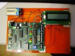
I connected a LCD screen directly to the test pin point and the +V/0V to the connections at the bottom right corner connections. It worked initially but became fainter with time. Any suggestions of how to test if they have been 'killed' or whether or not I have done something stupid. The backlight still works!
 

westaust55

Moderator
Have you checked the voltage at the connections where you take power for the display?

Those 9V batteries only have a capacity of around 200 mA and will not last long if powering a backlight as well.
The newer PicAxe chips can operate down to quite low voltages but LCD displays need 5V -no more and not much less. 4.5 Volts and they will "fade out". But the backlight will still glow.
 

Captain Haddock

Senior Member
I've connected serial lcd to that board with no problems using the middle pin of the connector (lower right) for the serial out and other two for lcd power, that was using a 9v wall adaptor for board power.
 

nick12ab

Senior Member
View attachment 11317
...It worked initially but became fainter with time.
Blame it on the linear regulator!
Rev-Ed don't provide the datasheet to the LCD but it looks like this one. From the datasheet, the "LCM" (liquid crystal module) uses 2mA and the backlight 300mA so that's a total of 302mA providing the correct forward voltage is used for the backlight. As there's 7 ICs on the trainer board, that might be 7mA so a total of 309mA. Let's say that the LEDs on the trainer board make this up to 350mA so that I can just use the 350mA discharge curve in the battery datasheet.

The battery appears to be an Energizer rechargeable (Google image search for '9v energizer rechargeable' shows a mix of batteries that look either like yours or like the one in the datasheet). According to the 7805 datasheet, its voltage drop is 2V so the input needs to be at least 7V. There's no mention of that diode on the AXE055 in the A XE055 datasheet but Rev-Ed put a series diode in the AXE033 so I'll assume they've done it again making the minimum input voltage now 7.7V.


Based on that discharge graph, the voltage will start to sag, well, instantly. If the diode is not in series with the 7805 then the voltage will sag after 6 or 7 minutes.

I also recommend shorting out the diode on the AXE033 by shorting the PWR jumper on the AXE033. And as you're using a high current backlight, you should switch to a switching regulator which will provide longer battery life, less heat output and greater efficiency. A LDO regulator is a linear regulator but with a very low voltage drop compared to the 7805 (and also switching regulators) and that would also be a good alternative to a 7805.
 
Thanks to everyone - you are all brilliant and need a gold star for the help!

It is the problem as you described. It does seem to be a battery problem. I have some Energizer batteries attached to the boards and they seem to work on the ones without the screens. However with the screen the boards work but not the screen. After buying some Duracell plus power batteries the screens again work. The voltage drop is approx 2-3volts.

Just to add another question into mix. What would be the best way to power the T4 boards knowing that it will be impossible to use external mains plug in power supplies? I will now not use the backlight facility as I can't afford to keep replacing the batteries. If anyone could create me a 'simple' idiot's circiut then I will be in your debt. I have no mains power sockets to actually plug things into - it is a new building and they physically prevent random devices being used in the labs. This means that these devices have to be powered via some form/combination of battery.


Thanks,

Robert
 

nick12ab

Senior Member
Just to add another question into mix. What would be the best way to power the T4 boards knowing that it will be impossible to use external mains plug in power supplies?
Multiple batteries in series - and switch to a switching regulator.

This might seem a stupid comments/question but ... Would using an 18M2 picaxe give me a few more mins/hours on these board?
No. You'd also need to use a regulator with lower voltage output and a negative voltage generator (which won't use much current) for the LCD contrast.
 

Technical

Technical Support
Staff member
The problem is the use of the PP3 battery. This is completely wrong style of battery for this type of application - see the PICAXE manual for more details about this. PP3s are designed for very low current smoke alarms and similar, not current hungry displays! Carefully peel a PP3 open in your lab, it's very educational for every student to see the 6 stacked coin cells inside the PP3 and compare one of these coil cells (1.5V) against the size of a AA battery (also 1.5V)...

Instead of using 9V and connecting through the 5V regulator, simply use 4.5V (3xAA cells) and connect them directly to the 5V rail instead (use OUT and GND connections instead on the power rail test point you are using). This will work much better.

Not using the display backlight will also make the batteries last much longer, you shouldn't need the backlight in a lab. Simply cut the backlight resistor on the PCB to turn it off.
 
Last edited:

Captain Haddock

Senior Member
The linear regulator on the T4 board should cope with a 12v car battery fine if you have facility to charge one occaisionally and last for ages, may get a bit hotter though.
The simplest is 3x 1.5v batteries after the regulator.
 

srnet

Senior Member
The current mentioned was 350ma, so for a fully charged car battery the regulator dissipation would be 8 watts.

With no heat sink on the regulator (I dont see one) the regulator junction temperature would be circa 225C.

It should not exceed 125C.
 
Top