Strobe Control

davefish55

New Member
Hello - I am thinking about a project that would use a Picaxe to control the flash of a small throw away camera strobe. There are quite a few hacks on the net involving these (and ample warnings about how you can really zap yourself on the caps that are in the circuit). See --- http://members.misty.com/don/samflash.html --- for a huge amount of information.

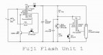
I can't find anything that shows how to drive the switches from a Picaxe. One example camera strobe circuit diagram is attached. My question is how to best drive the switches (S1 - Charge and S2 - Fire in the attached circuit)?

Should I use a small relay (like the Picaxe example circuit) -- if so, what will the contact rating need to be - I think the voltage on the S2 leg is around 300V, but it is not clear if the switch passes the full voltage to the strobe and I can't find where the current is called out. When these relays are shown in example circuits, they don't seem to show a part number, any example parts?

Would a thyristor (triac?) be better -- what does the circuit look like for driving a triac? I've also seen a comment where triacs are "easy to turn on, but hard to turn off". Or should I be thinking SCR -- again, how does this device get driven off an axe? Or should I use a SSR - opto-isolated?

Excuse me if these are ignorant questions. I've been digging around for answers on this forum and elsewhere before I post, but have not found anything definitive. And these strobe circuits look tricky enough, that it seemed time to ask the experts.

Thanks for any input.
 

Attachments

Tom2000

Senior Member
Howdy, Dave,

Probably a good, safe way to trigger the flash would be by means of a 600 volt SCR, driven from the Picaxe via an optoisolator.

I've attached a quick sketch showing how you might go about it.

Make sure that you don't make any electrical connections from the Picaxe to the flash. Just go through the opto as shown.

Good luck!

Tom
 

Attachments

davefish55

New Member
Stobe Circuit

Thanks for the circuit and help. Is there an opto part you like -- I see about 208 different ones up on Jameco ... maybe a 4N25 ? They seem to be 6-pin devices (I can see what is going on with the LED section, and one pin is unused, but what about the other 3 pins -- on the data sheet, I see Vcc, output and ground -- and the sheet doesn't give the pins assignments).
 

Tom2000

Senior Member
Howdy, Dave,

The opto demands aren't critical. Any of the 4N series, or whatever you can scrounge, should work in your app.

An opto normally has five active leads. Two for the LED, and three for the transistor's base, emitter, and collector. You normally leave the base floating, so you'll make four connections to each opto.

Good luck!

Tom
 

davefish55

New Member
Stobe control power supply

A few questions to add ... when I first build and test this project it will run off two independent battery power supplies - the standard 3 battery supply to the picaxe and the 1 battery (1.5V) supply in the flash circuit. Once working, I'd like to have it run off a DC output "wall wart" type supply. From poking around, it looks like a circuit that would use two voltage regulators off a 6VDC or 12VDC supply might be the way to go. Finding a 1.5V output regulator is a bit difficult. On this forum, there is a thread about "glow plug" power supply that seemed to offer a good example.

My questions - should I be worried about the current draw from the strobe circuit on the 1.5V leg when the flash is going off? It seems like the first transformer stage should isolate this (and the serious juice is in the capacitor, not being drawn from the battery). Do I need to protect the picaxe power leg ground from reverse voltage spikes when the strobe fires (and how is this done -- one or two diodes)? Do I need to worry about how close the strobe circuit is to the picaxe circuit (I'm thinking inductive pulse when the strobe fires)?

Thanks for any points/ideas.
 

Tom2000

Senior Member
Dave,

If you're going to be powering both the Picaxe and the flash from the same circuit, BE DARNED CAREFUL to address proper isolation between the two. And note that the flash uses a positive ground.

An LM317 regulator can work as low as 1.25 volts on the output, as I recall. (Check the data sheet...)

You don't have to worry (too much) about current spikes from the flash. As you mentioned, the flash cap does the heavy lifting. However, if you're using a 12 volt power supply regulated down to a (nominal) 1.5 volts, and if you're triggering the flash at a high rate, consider the LM317's power dissipation. It might seem absurd, but you might find yourself needing a heat sink for the 1.5 volt regulator.

Take reasonable precautions to bypass the Picaxe's power feed , and all should be well.

If you're careful, it should all work. If not, instant fried Picaxe.

Good luck!

Tom
 
Last edited:

davefish55

New Member
Positive Ground

Thanks for your continued assistance.

One question about the "positive ground" -- is this because the secondary on T1 is tied back into the positive side of the 1.5V battery? I was thinking I should try to isolate the two regulators (maybe the best solution would be to use two wall warts). Each regulator will have a ground leg - are you saying that I need to treat the positive and ground legs on the regulator differently for the strobe circuit (1.5V) than the picaxe one (5V)?
 

BeanieBots

Moderator
It's only the HV side which is +ve Gnd. You just need to be aware of which way current flows through the fire switch.
I have my doubts if you will ever be able to make it trouble free unless you have at least some experience of wiring such circuits.
The current, voltage & emf spikes are going to be massive. Ground wiring and decoupling are going to be VERY critical.
Turning on a fourescent tube can take out a PICAXE from 3 feet away if it's not properly protected. This will be much worse but not impossible.

I think I'd go with Tom2000's power suggestions. Again, bear in mind that the peak switching current of the inverter will be very high compared to the average current, so although I doubt you will need a heatsink, the LM317 will not be able to supply the peak current and will require a good quality low ESR reservoir cap on both sides.
 

davefish55

New Member
Thanks

OK -- I see, now that I am looking at the dots on the transformer symbols.

Once I start to play, I'll post the results of my picaxe cooking experiments.

First I need to build my capacitor discharging tool (a 1M-ohm resistor on the end of a wooden stick) ...
 

davefish55

New Member
SCR R Value

One question - on TOM2000's diagram, the SCR gate leg is connected to the OPTO output, which is tied to the flash ground across resistor "R". How do I find out what value I should use for R?

From reading in the flash web sites, it looks like the transformer leg that the OPTO will be connected to will see somewhere between 90-150V when the neon starts to glow. If I want to keep the current through the gate low (10mA), would I use something like a 1K resistor?

Thanks.
 

Tom2000

Senior Member
Dave, you need to look at the data sheet for the SCR you're using, and measure the voltages in the flash HV circuit. Choose a value of R that will keep the gate current at a safe level.

Tom
 

davefish55

New Member
SCR

I'm using the C122M1, which is a 600V SCR. The sheet shows a gate trigger current of 25mA and gate trigger voltage of 1.5V at 25C. So if I read the voltage across the flash switch when it is charged, then that would tell me what R should be if I use the trigger current spec.

For example, if the voltage reads 130V, then I'd get: 130/0.025 = 5.2K

... which is where I get confused, what does the 1.5V in the spec. mean, won't that leg have more than 1.5V across it (like 130V)? This is also where I am, no doubt, showing my ignorance of transistor operation and design.

Thanks again.
 

Tom2000

Senior Member
Don't worry about that 1.5 volt number, Dave. The opto will drive it OK.

That 25 ma gate current is a maximum, I'd think, so you'd want an R value somewhere between 10 K and 27 K.

Good luck!

Tom
 

g6ejg

New Member
Hi,

I am just in the process of doing exactly the same thing - controlling a fuji disposable camera flash unit with a picaxe. I wonder if you got it to work in the end?
 

fernando_g

Senior Member
If you can get your hands on a TLP741J, which is a 600v SCR output optocoupler, , you could further simplify the circuit.
But this circuit would also work with 400v SCR couplers, which may a little easier to find.
 

g6ejg

New Member
Ive got the picaxe driving an MC3020 thyristor driver which in turn drives a C106D - this does work in so far as the thyristor "fires" everytime ( although using the thyristor with the MC3020 is probably overkill in this application). However the actual camera flash only fires occasionally and Ive not yet worked out why it doesnt fire everytime - hence asking if the original poster had actually got it to work.

As an aside, this is inspired by another posting on the forum - the picaxe is being used to detect an infrared beam being broken and then in turn firing the flash.
 

fernando_g

Senior Member
I think you mean MOC3020, a 400 volt TRIAC optocoupler.

If that is indeed the case, you require at least 15 mA for the LED drive to trigger reliably.
Also since the device can handle a repetitive current of 1 amp, 1 msec pulse @ 120 Hz, that you could trigger the transformer directly.
 
Last edited:

g6ejg

New Member
I do of course mean a MOC3020 - it was a typo on my part, and yes, as I wrote that and the 106D is overkill. I added the 106D as an afterthought as the MOC3020 wasnt triggering the flash everytime.

As I wrote, the MOC3020 ( and hence 106D) is firing everytime but it doesnt fire the flash everytime - the MOC3020 is driven by the picaxe so current is not an issue. Looks like its some issue with the thyrister behaving differently to the mechanical switch that it replaces
 
Top