techElder
Well-known member
You must not have anything else to do if you are anticipating explaining this program problem! 
There's really no way to test the program without having the particular hardware that I have, but suffice it to say that I've exercised and created quite a few macros and subroutines using the SPI style interface on the module to display numbers (8-digits) and light LEDs (8). SPIOUT statements worked fine with my 20X2. Then it came time to read the switches (8).
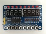
The SPIIN statement in the second subroutine would not read the data from the module. So, I went to modifying the bit-bang example code from "BASIC Commands" for SHIFTIN/SPIIN because I have to read four bytes to get the status of the eight switches. Once I got the code right and OR'd the bits correctly into the output byte, I'm done because it works great.
However, its a mystery to me (because I'm not privy to the code involved with SPIIN) why the example code works, but the SPIIN code does not. One thing I couldn't do is try the "idle high" option, because it wouldn't compile with my 20X2 version according to the error message.
What happened to SPIIN?
There's really no way to test the program without having the particular hardware that I have, but suffice it to say that I've exercised and created quite a few macros and subroutines using the SPI style interface on the module to display numbers (8-digits) and light LEDs (8). SPIOUT statements worked fine with my 20X2. Then it came time to read the switches (8).
Code:
; "C:/Users/Paul/Documents/SensorNetwork/spiin_bit_bang_test.bas"

#no_data
#no_table

; ~~~~~ SYMBOL DEFINITIONS ~~~~~
; Required for all routines. Change pin numbers/bits as required.
; Uses variables b7-b13 (i.e. b7,w4,w5,w6). If only using 8 bits
; all the word variables can be safely changed to byte variables.

;***** Sample symbol definitions *****
symbol sclk = B.3				; clock (output pin)
'symbol sdata = 7			; data (output pin for shiftout)
symbol serdata = pinB.4			; data (input pin for shiftin, note input7)
symbol counter = b7			; variable used during loop
symbol counter2 = b8
'symbol mask = w4			; bit masking variable
'symbol var_in = w0			; data variable used durig shiftin
'symbol var_out = w6			; data variable used during shiftout
symbol var_in = w6			; data variable used durig shiftin
symbol var_out = w0			; data variable used during shiftout
symbol bits = 8				; number of bits
symbol MSBvalue = 128			; MSBvalue =128 for 8 bits, 512 for 10 bits, 2048 for 12 bits)

'Pin assignments
symbol d_strobe               = B.2          ; strobe
'symbol d_clk                  = B.3          ; clock (output pin)
symbol d_data                 = B.4          ; data (output pin for shiftout)
symbol READ_IN                = 0x42         ; read incoming byte

'input serdata
output d_data
	let var_in = 0
   let var_out = 0

do
   gosub shiftin_LSB_Pre ; works like a champ!
   'gosub spi_LSB_Pre
   'gosub shiftin_MSB_Pre ; works but bits are backwards
   'gosub shiftin_LSB_Post ; does not work
loop
end

shiftin_LSB_Pre:
   low d_strobe                              ; activate the strobe
   spiout sclk, d_data, LSBFirst_L,(READ_IN) ; set the module for reading the switches
   input d_data                              ; change the data pin to INPUT
	let var_in = 0                            ; clear the bit variable
	let var_out = 0                           ; clear the byte variable
   for counter2 = 0 to 3                     ; read 4 bytes total
   	for counter = 1 to bits		            ; number of bits
   	  var_in = var_in / 2		            ; shift right as LSB first
   	  if serdata <> 0 then
   	    var_in = var_in + MSBvalue		   ; set MSB if serdata = 1
   	  end if
   	  pulsout sclk,1		                  ; pulse clock to get next data bit
   	next counter                           ; test next bit
      var_out = var_in << counter2 OR var_out; summarize the bits into the byte
   next counter2                             ; next byte
   ' debug output
   sertxd("var_out: ",#bit7,#bit6,#bit5,#bit4,#bit3,#bit2,#bit1,#bit0,cr,lf)
   high d_strobe                             ; inactivate the strobe
   output d_data                             ; change the data pin back to OUTPUT
	return                                    ; the 8 switch status in bits of var_out

spi_LSB_Pre:
   low d_strobe                              ; activate the strobe
   spiout sclk, d_data, LSBFirst_L,(READ_IN) ; set the module for reading the switches
   input d_data                              ; change the data pin to INPUT
	let var_in = 0                            ; clear the bit variable
	let var_out = 0                           ; clear the byte variable
   for counter2 = 0 to 3                     ; read 4 bytes total
      spiin sclk, d_data, LSBPre_L,(var_in)
;   	for counter = 1 to bits		            ; number of bits
;   	  var_in = var_in / 2		            ; shift right as LSB first
;   	  if serdata <> 0 then
;   	    var_in = var_in + MSBvalue		   ; set MSB if serdata = 1
;   	  end if
;   	  pulsout sclk,1		                  ; pulse clock to get next data bit
;   	next counter                           ; test next bit
      var_out = var_in << counter2 OR var_out; summarize the bits into the byte
   next counter2                             ; next byte
   ' debug output
   sertxd("var_out: ",#bit7,#bit6,#bit5,#bit4,#bit3,#bit2,#bit1,#bit0,cr,lf)
   high d_strobe                             ; inactivate the strobe
   output d_data                             ; change the data pin back to OUTPUT
return ; the 8 switch status in bits of var_outHowever, its a mystery to me (because I'm not privy to the code involved with SPIIN) why the example code works, but the SPIIN code does not. One thing I couldn't do is try the "idle high" option, because it wouldn't compile with my 20X2 version according to the error message.
What happened to SPIIN?