The whole idea is that you have an impedance such that the average current isn't too much for the PICAXE o/p driver.
My Manual 3 show 10uF (pos to PICAXE pin) in series with a speaker marked 40R.
Obviously with an inductive device all this can get complicated if you want to get carried away, so don't.
So, consider that as your MINIMUM requirement wrt impedance and output load.
Therefore if your speaker is too loud then add some ohms with a small resistor.
If it is too quiet then you will have to amplify it, using electronics and/or a clever enclosure.
I realise that's not Rocket Science, but so many people forget about it.
And if you have a spare half-hour, have a read up about using capacitors/resistors in filter circuits.
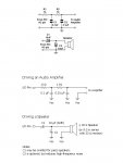
A couple of example circuits from other places are shown below.
Like everything , once you have sussed out the reason 'why' something is required then you can relax about your design.
Let me just add one note; 10 years ago when I tried a Stamp I followed the Parallax example circuit (the bottom one below). My Stamp went bonkers. Not the Stamp's fault. It was my particular cheapo speaker. It was bunging lots of back emf into pin. A small series resistor cured it.
Thank goodness I had a 'scope and didn't have to wait 3 weeks for a forum reply.
")