Hello all, I have a new project I am working on and hit a snag. I am in the process of making an alarm clock out of an NES controller. I am using four seven segment displays (multiplexed) to show time obtained from DS1307 RTC. For now, I am just trying to display time on the seven segment display.
Now I did manage to obtain time data and convert it to display properly (bcd-->ascii-->decimal-->display mask). The problem is when time is displayed, it is out of order.
For example, say I am displaying the time 13:42. I would first display "1" then "3" then "4" then "2" which I call digit1, digit2, digit3, and digit4 respectively. However, when this is attempted, I get the display to show 34:21. It is rather odd, all of the time data is there but switched up in different places. To make sure it was not my code that converted time to display, I only turned on one digit at a time. So say I only chose to display the "3" in the same example, I would indeed get it to sit in the right spot, meaning x3:xx where x means the digit of the display is off (leds off). I also tried this with all places and they all sit in the right spot. However, say I now try to now turn on only two digits at a time, say, only the hour component, it would get switched up again and display 31:xx.
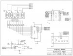
Code is below (sorry for the code size, most of it is just notes for myself) as well as a schematic. The schematic shows a display pre-wired to be multiplexed, my setup is equivalent but has separate seven segment displays, meaning, I wired it up to be multiplexed.
Now I did manage to obtain time data and convert it to display properly (bcd-->ascii-->decimal-->display mask). The problem is when time is displayed, it is out of order.
For example, say I am displaying the time 13:42. I would first display "1" then "3" then "4" then "2" which I call digit1, digit2, digit3, and digit4 respectively. However, when this is attempted, I get the display to show 34:21. It is rather odd, all of the time data is there but switched up in different places. To make sure it was not my code that converted time to display, I only turned on one digit at a time. So say I only chose to display the "3" in the same example, I would indeed get it to sit in the right spot, meaning x3:xx where x means the digit of the display is off (leds off). I also tried this with all places and they all sit in the right spot. However, say I now try to now turn on only two digits at a time, say, only the hour component, it would get switched up again and display 31:xx.
Code is below (sorry for the code size, most of it is just notes for myself) as well as a schematic. The schematic shows a display pre-wired to be multiplexed, my setup is equivalent but has separate seven segment displays, meaning, I wired it up to be multiplexed.
Code:
#rem
================================================================================

    File........... NES_Controller_Alarm_Clock.bas
    Purpose........ Alarm Clock Functionality
    Author......... Joseph Corleto
    E-mail......... jc269@njit.edu
    Started........ 05/14/2012
    Finished....... --/--/----
    Updated........ --/--/----

================================================================================
  Updates
================================================================================

#endrem
'===============================================================================
'  EEPROM Data
'===============================================================================

'===============================================================================
'  Constants
'===============================================================================
symbol bits 	=     8		' number of bits
symbol MSBvalue   = 	128
' MSBvalue (=128 for 8 bits, 512 for 10 bits, 2048 for 12 bits)
symbol setsecond	=	$14	'set the current second here
symbol setminute	=	$45	'set the current minute here
symbol sethour	=	$20	'set the current hour here
symbol setday	=	$05	'set the current day here
symbol setdate	=	$01	'set the current data here
symbol setmonth	=	$03	'set the current month here
symbol setyear	=	$12	'set the current year here
symbol control	=	$10	'set the control here

'===============================================================================
'  Variables
'===============================================================================
symbol second 	=	b0	'holds what second it is
symbol minute	=	b1	'holds what minute it is
symbol hour		=	b2	'holds what hours it is
symbol day		=	b3	'holds what day it is
symbol date		=	b4	'holds what date it is
symbol month	=	b5	'holds what month it is
symbol year		=	b6	'holds what year it is
symbol counter    =     b7	'variable used during loop
symbol hourtens   =     b8	'holds tens place of the hour
symbol hourones	=	b9	'holds ones place of the hour
symbol minutetens =     b10	'holds tens place of the minute
symbol minuteones	=     b11	'holds ones place of the minute
symbol var_out    =     w6	'data variable used during shiftout
symbol mask	      =     w7 	'bit masking variable

'===============================================================================
'  Pin Declarations
'===============================================================================
'Inputs:

'Outputs:
symbol sdata   = c.0	'serial data to feed into 74HC595(output pin for shiftout)
symbol latch   = c.1	'latch pin for 74HC595
symbol sclk    = c.2	'clock for 74HC595 (output pin)

symbol digit1  = b.0	'control pin for the hour's tens place
symbol digit2  = b.2	'control pin for the hour's ones place
symbol digit3  = b.3	'control pin for the minute's tens place
symbol digit4  = b.5	'control pin for the minute's ones place

'===============================================================================
'  Initialization
'===============================================================================
#picaxe 18m2     'place directive here
setfreq m32	     'run internal oscillator @ 32MHz

#rem
Note:This portion of the program is only needed to program the current time and
     date. Uncomment this code for a fresh DS1307. If the DS1307 under test
     already has current time preloaded, leave the bottom code commented.
#endrem

Set_Time:
'hi2csetup i2cmaster,%11010000,i2cslow,i2cbyte	'paramters set,18M2 is master
'hi2cout 0,(setsecond,setminute,sethour,setday,setdate,setmonth,setyear,control)

'===============================================================================
'  Main
'===============================================================================
Read_Time:
do

hi2csetup i2cmaster,%11010000,i2cslow_32,i2cbyte   'paramters set,18M2 is master

hi2cin 1,(minute,hour)		'obtain minute and hour information from DS1307

Convert_Time:
'-------------------------------------------------------------------------------
bcdtoascii hour,hourtens,hourones		'convert hour data to ascii

let hourtens    = hourtens - $30		'convert "hourtens" to decimal

'convert "hourtens" to be displayed on seven segment
lookup hourtens,(63,6,91,79,102,109,125,39,127,103),hourtens

let hourones    = hourones - $30		'convert "hourones" to decimal

'convert "hourones" to be displayed on seven segment
lookup hourones ,(63,6,91,79,102,109,125,39,127,103),hourones

'-------------------------------------------------------------------------------
bcdtoascii minute,minutetens,minuteones	'convert minute data to ascii

let minutetens  = minutetens - $30		'convert "minutetens" to decimal

'convert "minutetens" to be displayed on seven segment
lookup minutetens,(63,6,91,79,102,109,125,39,127,103),minutetens

let minuteones = minuteones - $30		'convert "minuteones" to decimal

'convert "minuteones" to be displayed on seven segment
lookup minuteones,(63,6,91,79,102,109,125,39,127,103),minuteones

'-------------------------------------------------------------------------------

Display_Time:
low digit1				'turn on tens place of the hour
let var_out = hourtens		'prep for shift out sub-routine
gosub shiftout_MSBFirst		'display tens place of the hour
input digit1			'turn off tens place of the hour

low digit2				'turn on ones place of the hour
let var_out = hourones		'prep for shift out sub-routine
gosub shiftout_MSBFirst		'display ones place of the hour
input digit2			'turn off ones place of the hour

low digit3				'turn on tens place of the minute
let var_out = minutetens      'prep for shift out sub-routine
gosub shiftout_MSBFirst		'display tens place of the minute
input digit3			'turn off tens place of the minute

low digit4				'turn on ones place of the minute
let var_out = minuteones      'prep for shift out sub-routine
gosub shiftout_MSBFirst		'display ones place of the minute
input digit4			'turn off ones place of the minute

loop

'===============================================================================
'  Sub-Routines
'===============================================================================
' ***** Shiftout MSB first *****
' Shift out the data MSB first from variable var_out
' Using clock output pin sclk
' Using data output pin sdata

' Note the number 128 (used twice) is the mask byte for MSB of 8 bits
' If using 10 bits use 512, 12 bits use 2048 etc

shiftout_MSBFirst:
	for counter = 1 to bits			' number of bits
		mask = var_out & MSBValue 	' mask MSB
		high sdata 				' data high
		if mask = MSBValue then skipMSB
		low sdata				' data low
skipMSB:
		pulsout sclk,1 			' pulse clock for 10us
		var_out = var_out * 2 		' shift variable left for MSB
	next counter
	pulsout latch,1
	return