Setting up HI2CSETUP Commands in a block

westaust55

Moderator
What are the limitation on using a predefined group of HI2CSETUP commands?

I have a number of HI2CSETUP commands in a block in the initialization part of my program.

I have found that if I have the setup command for EEPROM first it does work,
whereas if the same line is the last setup command it does work correctly.

For example, with the following commands, a read of the EEPROM does not function correctly:
Code:
Init:  HI2CSETUP  i2cmaster, EEPROM_0, i2cfast, i2cword
       HI2CSETUP  i2cmaster, expand_0, i2cslow, i2cbyte
       HI2CSETUP  i2cmaster, expand_1, i2cslow, i2cbyte
       HI2CSETUP  i2cmaster, rtc1307,  i2cslow, i2cbyte
       HI2CSETUP  i2cmaster, cmps03_0, i2cslow, i2cbyte
       HI2CSETUP  i2cmaster, srf008_0, i2cslow, i2cbyte
       HI2CSETUP  i2cmaster, spe030_0, i2cslow, i2cbyte

Whereas the following sequence will work for the IO expanders AND the reading of the EEPROM:
Code:
Init: HI2CSETUP  i2cmaster, expand_0, i2cslow, i2cbyte
       HI2CSETUP  i2cmaster, expand_1, i2cslow, i2cbyte
       HI2CSETUP  i2cmaster, rtc1307,  i2cslow, i2cbyte
       HI2CSETUP  i2cmaster, cmps03_0, i2cslow, i2cbyte
       HI2CSETUP  i2cmaster, srf008_0, i2cslow, i2cbyte
       HI2CSETUP  i2cmaster, spe030_0, i2cslow, i2cbyte
       HI2CSETUP  i2cmaster, EEPROM_0, i2cfast, i2cword

With the first group of commands above, if I repeat the line
Code:
HI2CSETUP  i2cmaster, EEPROM_0, i2cfast, i2cword
Just prior to the EEPROM read command, then the EEPROM data is read (correctly)

Any thoughts or known isssues? :confused:
 

BCJKiwi

Senior Member
Normally there would only one hi2cSetup command for the whole program and never repeated.

The read/write commands then need to include the chip address.

However if the configuration of the devices differs e.g. the byte and word situation, then the hi2cSetup will need to be issued again ONLY when changing device types, not for for any other reads/writes.

i.e. ensure the bus is in the correct state before issuing a read or write.
 

westaust55

Moderator
Thanks BCJKiwi.

That's a bit of a downer really. :(

Each of my HI2CIN and HI2COUT commands does include the device ID. For example:

HI2COUT [expand_0], (pattern)

and

HI2CIN [EEPROM_0], keyval, (keychar)


A bit of a potential programming issue as I have a read from an EEPROM in an interupt routine which might happen at any time could be just prior to a command to write to an i2c IO expander or read from some other i2c bus device.
So each i2c activity may be incorrectly set up if/as the PICAXE BASIC does not keep a specific record of every HI2CSETUP for each ID/Address.

Looks like I may have to go back to inserting HI2CSETUP commands just prior to each i2c bus action to be on the safe side as my program is working with a range of i2c devices with no guarantee on the sequence they are communicated with (due to user interface/menu allowing access in any order via the keypad).
 

Technical

Technical Support
Staff member
The setup command sets the bus condition at that time. You cannot have multiple lines together like this - everything but the last one is wasted code!

You should also not mix fast and slow devices on the same bus - so run the fast device in slow mode so all communication is at the slow rate. Otherwise devices such as the DS1307 may misbehave.

In this case the only device that is a different mode completely is the eeprom, so you only need hi2csetup before and after eeprom writes - eveything else can just use the slave address prefix in the hi2cin/out command.

e.g.

Code:
HI2CSETUP  i2cmaster, expand_0, i2cslow, i2cbyte
..
...
...
HI2COUT [expand_0], (pattern)
HI2COUT [rtc1307], (pattern)
...
...
...
HI2CSETUP  i2cmaster, EEPROM_0, i2cslow, i2cword
HI2CIN keyval, (keychar) 
HI2CSETUP  i2cmaster, expand_0, i2cslow, i2cbyte
...
...
HI2COUT [rtc1307], (pattern)
 

hippy

Ex-Staff (retired)
Looks like I may have to go back to inserting HI2CSETUP commands just prior to each i2c bus action to be on the safe side as my program is working with a range of i2c devices with no guarantee on the sequence they are communicated with (due to user interface/menu allowing access in any order via the keypad).
That's the only way to do it. The I2C interface will only ever be configured according to the last HI2CSETUP command issued. If you need to switch devices you need to issue a HI2CSETUP to use that particular device.
 
That's the only way to do it. The I2C interface will only ever be configured according to the last HI2CSETUP command issued. If you need to switch devices you need to issue a HI2CSETUP to use that particular device.
I am using 2 MAX6953 devices. Then, if I understood it right, I will use HI2CSETUP once and issue the write command changing the MAX6953 as appropriate. Am I right?
 

hippy

Ex-Staff (retired)
I think you'll have to issue a HI2CSETUP before each MAX6953 because each will have a different I2C Device Address. The only thing you can specify in an I2CWRITE is the data to write and the location of where to put it. To select the Device you want to write to next requires the HI2CSETUP command ... unless the MAX6953 does something unusual.
 

Technical

Technical Support
Staff member
hippy, you've missed the optional 'change the default slave address' [slaveaddress] parameter at the start of the hi2cin and hi2cout commands . If the bus parameters (speed and byte/word) don't change, you can change the slave within the hi2cout/in commands without using another hi2csetup, which is far more code compact. So for the MAX6953 simply change the slave address within the first hi2cout/hi2cin command to that chip.
 

hippy

Ex-Staff (retired)
I had indeed missed the ability to change slave address in the HI2CIN/I2COUT commands, and mixed my HI2C with I2C :)
 

westaust55

Moderator
Thanks Technical,

Much clearer now.

I had been getting comments about having “generally one HI2CSETUP command at the start of the program” when I had them distributed.

Might have been clearer if the manual 2 stated only the last HI2CSETUP applies with respect to speed and byte/word data size.

Noted about i2c bus speed being uniform for all devices at the lowest denominator (slow).

I am trying to get a DS1337 and with an SOIC to DIP adapter will be a i2cfast (400KHz) drop in replacement for the slow DS1307.

But with several EEPROMs in my system each called from different parts of the program think I will be better to stick with several distributed HI2CSETUP commands at relevant parts of the program.


In the PICAXE manual 2 on page 51 some other components, for example the CMPS03 compass module, are promoted as being suitable for a fast i2c bus speed (400kHz) but looking at the manufacturers (Devantech) website and forum I note they promote them as only being slow (100kHz) rated.

One example from the Devantech forum:
by chris (moderator) on Thu May 24, 2007 12:05 pm
I assume the following line line from the CCS compiler puts the clock speed to 400khz:
#use i2c(Master,Fast,sda=PIN_C4,scl=PIN_C3)

The CMPS03 will not operate correctly at this frequency, try slowing the clock speed to 100khz.
Gerry (Gerald Coe) the Devantech owner/manager ? Has also made the same comment


CMPS03 I2C Value reading problems
by Gerry on Mon Oct 15, 2007 11:26 am
ritchie wrote
:Hi,

after i made the bits of the 16 Bit value visible, i saw, that the failure only was active, when the low byte of the value was set to 0xff.

After re-reading the, when low byte = 0xff, the compass value is fine.

But my i2c function works with several other chips fine, so i guess it will happen something with the compass ?

Regards
Ritchie

(response by Gerry)
Make sure your SCL speed is 100khz or less and that the I2C master you are using implements the I2C bus hold. There are some implementations of bit bashed I2C masters that ignore the bus hold.
 
Last edited:

westaust55

Moderator
In summary and as an enhancement to what is written in PICAXE manual 2 pages 48 to 51:

(maybe Rev-Ed can update their manual at the next revision to make it a little more self explantory for PICAXE i2c newbies)

If you are using a single slave i2c device alongside your PICAXE master you generally only need one hi2csetup command within a program. After the hi2csetup has been issued, hi2cin and hi2cout can be used to access the slave i2c device.


When using multiple i2c devices having the same speed AND address length (ie i2cbyte or i2cword for all devices) you can change the default slave address within the hi2cin or hi2cout command.


When using multiple devices with different speeds the recommendation is to use the lowest speed of all the devices on the bus for all i2c bus communications. Therefore, if there are devices rated for i2cslow and i2cfast then always use the i2cslow bus speed in all hi2csetup commands to avoid slow speed devices becoming problematic during fast reads.


When using multiple devices with different address lengths , then a new hi2csetup command needs to be issued prior to the first access to a device with a different address length to the last accessed i2c device. This situation will likely occur when EEPROMS such as the 24LC256 (fast speed rating) are used as well as devices such as RTC’s, ultrasonic sensors, compass modules and speech synthesis modules.

See the table at the bottom of page 51 in manual 2 for some typical i2c bus speed and address length configuration details.
 

BCJKiwi

Senior Member
The Devantech CMPS03 Compass Module documentation indicates how to make it run at 400khz or 1MHz
"The I2C interface does not have any pull-up resistors on the board, these should be provided elsewhere, most probably with the bus master. They are required on both the SCL and SDA lines, but only once for the whole bus, not on each module. I suggest a value of 1k8 if you are going to be working up to 400KHz and 1k2 or even 1k if you are going up to 1MHz. The compass is designed to work at up to the standard clock speed (SCL) of 100KHz, however the clock speed can be raised to 1MHZ providing the following precaution is taken;
At speeds above around 160KHz the CPU cannot respond fast enough to read the I2C data. Therefore a small delay of 50uS should be inserted either side of writing the register address. No delays are required anywhere else in the sequence. By doing this, I have tested the compass module up to 1.3MHz SCL clock speed."

Have just received some DS1337s which will be mounted directly onto 8 pin DIP machined sockets and will be testing RTC, accelerometer, compass, uALFat, and MCP23017s at 400kHz in the next day or two.
 

westaust55

Moderator
Hi BCJKiwi,
Yes, noted that other documentation shows capability of faster operation. The manual from wich your extract comes is current and dated March 2007 whereas the manufacturer in May and October 2007 (per my extracts) is saying use 100kHz. Seems to be a lot of conflict between documentation in some quarters.


Glad to see you have received the DS1337 RTC’s

I have received some very small SOIC8 to DIP8 adapter PCB’s (no bigger than area of a DIP socket) and likewise hope to have some DS1338’s inside another week. These are the drop in replacement for DS1307 (without the two alarms of the DS1337).

As I picked up a number of these adapters (cheaper by the dozen ? – actually min quantity was a dozen).
If you are interested in one to try, I am happy to post one your way – happy to go on a pay if you like it basis as not a lot in it.
 
Last edited:

BCJKiwi

Senior Member
Just been back to the latest documentation on the website which has the exact same text as that which I quoted above. I guess only the testing will tell.

I also note this newer documentation also shows how to increase the compas scan rate which might be of benefit if clocking faster - not sure but could be worth a try if there are problems.

Higher bus speed pull ups seem very low values - standard is 4k7 to 10k (for 100kHz). Have scoped this previously on 100kHz and the effect of the reduced pull up is to bring the bus line high faster which is what is required when the clock speed is increased.

The wave form shows a relatively slow rise time and a very rapid fall. Will check it out once I have the system up and running at the new speed.

The objective for me is to reduce the overall program cycle time but it will be very interesting to see what effect a change from 100kHz to 400kHz actually makes in the over all program speed. Don't really know what proportion of the cycle time is spent working on the i2c bus but will soon find out.
Also have a trade off to consider as there will be about 600 to 800 mm of cable between two circuit boards so the bus will have some length and the slower the bus the more reliable it will be with the increased length.

Thanks for the offer on the adapters but have the 16 pin So version of the DS1337 with internal crystal and will simply solder it directly onto the top of an 8pin socket. The 16pin SO is the same width/length as the 8pin dip at 0.05" pitch. Will bend down the legs 1,3 solder a wire onto leg 2 and solder it into pin3. Also solder leg7 into pin4 and cut off the other NC pins. ditto on the other side.
 
Last edited:

BCJKiwi

Senior Member
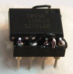
DS1337C on 8 Pin DIP

Soldered up the DS1337C 16 pin SO to an 8 Pin Dip as discussed - works a treat (see attached photo). The only code change applied was to change the register number for the configuration of the RTC.

Ran tests at i2cslow_16 for the 28X1 (as before).
3500 byte program cycles 12-13 times per sec including writes to uALFAT.

Changed to i2cfast_16
Found some instability so checked the i2c waveform on the scope. Found that the rise was slow and barely making full 5V with the 2k2 pullups already in place so changed to 1k pullups. Bus rises to full 5V in about half the available time.

Circuit stable and code cycles/sec rose to a consistent 15.
This equates to around 15% improvement in cycle time in a 3500 byte program. So I figure this would be a worthwhile speed improvement - specially on programs with more hi2c in/outs than the approx 20 in this program.

Made no changes to the code for the CMPS03
Also the uALFAT was happy at this speed without any changes required.

As my target is a guaranteed 10 cycles/sec, will reserve final judgment until tests are carried out with final builds completed and the extended i2c Bus implemented.
 

Attachments

Last edited:

westaust55

Moderator
The use/need for lower value pull-up resistors is in line with what has been proposed by Devantech and others for higher i2c bus speeds. As you mentioned in an earlier post it is linked to allowing the voltage waveform to rise faster.

The speed increase you have seen (at 15%) is reasonable compared to the incremental increase a desktop PC gets with a significant CPU speed increase.

Your SIOC to DIP8 conversion looks good and compact.

I have done a few tests using the i2cfast parameter with the 100kHz rated PFC8574 8-bit IO expanders and had no obvious problems at 400kHz.
So in theory if I get the surface mount DS1338 RTC and solder onto the adapter bord I have as drop in replacement for the DS1307 with a like change in i2c pull up resistors stand a good chance of being able to operate all at 400kHz.
 
Top