Serout / Serin help!?!

kredhead

New Member
I am making a personal safety bracelet and want it to be able to send out a signal via a radio transmitter when it is activated. I also want to set up the reciever module which will show that the signal has been sent and received.

I have been trying to use 2 x 08m chips to work this.

The code I have been using for the transmitter unit (transmitter chip) is -

main:
if pin3=0 then alarm
if pin2=0 then batterylight
goto main

batterylight:
high 4
pause 1000
low 4
goto main

alarm:
let b2 = 22
let b3 = 36
let b4 = 48
serout,T2400, (b2)
serout,T2400, (b3)
serout,T2400, (b4)
pause 1000
goto main

The code I have been using for the receiver unit (receiver chip) is -

main:
input 1
serin 1,T2400, b2
if b2<> 22 then goto main
serin 1,T2400, b3
if b3<> 22 then goto main
serin 1,T2400, b4
if b4<> 22 then goto main
high 2
pause 1500
low 2
goto main


But when I link them up on two experiment boards and try and get them to work together and communicate it doesn't work.

I was wondering if anyone would be able to help please as this is for my a level project?!?
 

eclectic

Moderator
Welcome to the Forum.

First very quick response.

Please post your circuit(s) / schematics.

2nd. Have you tested the program in the Simulator?
(I have. And, err your first program won't work.)

3rd. Could you please describe what you want the
programs to do?

e
 
Last edited:

kredhead

New Member
For the transmitter programme when the switch connected to pin2 is pressed that an LED turns on (that bit works although I wrote pin2=0 instead of pin2=1 on my post!)

When pin3=0 I want to have a signal sent out of one of the pins which can then be picked up by the second picaxe chip. When the second chip receives a signal I want an LED to light up.

I think its the alarm section of this code which doesnt work and is where I need help!?

main:
if pin3=0 then alarm
if pin2=1 then batterylight ' have corrected this bit
goto main

batterylight:
high 4
pause 1000
low 4
goto main

alarm:
let b2 = 22
let b3 = 36
let b4 = 48
serout,T2400, (b2)
serout,T2400, (b3)
serout,T2400, (b4)
pause 1000
goto main

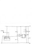
I have attached my circuit diagram for the bracelet/transmitter code.

For the receiver I only need to set it up on the experiment board to show the signal is being sent.
 

Attachments

eclectic

Moderator
Just to be certain,
could you re-post the circuit diagram S
(Tx and Rx)

Larger
and clearer
and correct way up
please?

And Manual 2, page 158 for Serout syntax
e
 
Last edited:

kredhead

New Member
This is the transmitter circuit diagram, have tried to make it bigger

What is (Tx and Rx) - I'm new to this!

I did read pg 158 but got confused from it and ended up with the code which I put above.

I'm not being ditzy I just find programming a bit confusing but once I understand how to use the codes then I'm fine! Honest.
 

Attachments

lbenson

Senior Member
Tx is transmit
Rx is receive

As e suggested, run your code in the simulator (download the Program Editor if necessary--it contains the simulator). That will tell you where the errors are which prevent the program from compiling, and will also enable you to step through the logic of your program to see how it will work in reality.
 

kredhead

New Member
Thanks!

Will try looking through this tomorrow at school and see if I can get it working and get my head around it.
 

kredhead

New Member
Oh quick question

Does it matter what numbers I put in the brackets and do I also need to put b1 into the brackets as well?
 

westaust55

Moderator
Welcome to the PICAXE forum.

1. Firstly, your SEROUT command needs to specify the pin number as well.
that is serout 0, T2400, (b2)
2. You may find it necessary to "pre condition" the radio transmitter with a series of 1's and 0's.

3. The receiver may not be fast enough to pick up the three separate data transmissions.


Instead of:
serout,T2400, (b2)
serout,T2400, (b3)
serout,T2400, (b4)

try

serout 0, T2400, (85, 85, 85, "ABC", b2, b3, b4)

maybe leave out the ABC part until you get something visible working.


then at the receiver

SERIN pin, T2400, ("ABC"), b2, b3, b4
followed by the IF...THEN tests.

and leave out the ABC part when not in the transmitter part.
 

kredhead

New Member
Ok I have tried doing the following codes

Transmitter

main:
let b0=1
serout 0, T2400, (85,85,85,85,"ABC",b0)
pause 100
goto light
light:
high 2
pause 1000
low 2
pause 1000
goto main
*
receiver

main:
serin 3,T2400,("ABC"),b0
if b0=1 then light
goto main
light: high 4
*pause 1000
*low 4
*pause 1000
*goto main


and it didnt work

I then tried to really simplify it and tried -

transmitter

main:
let b0=1
serout 0,N2400,(b0)
goto main
*
receiver

main:
serin 3,N2400, (b0)
if b0=1 then light
goto main
light: high 2
*pause 1000
*low 2
*pause 1000
*goto main


which didnt work either

Help!?!? Where am I going wrong?
 

Peter M

Senior Member
in post# 13 westy gives a pretty good clue!:eek:

1. Firstly, your SEROUT command needs to specify the pin number as well.
have a good look at your circuit......... what pin is connected to data on the Tx ??????????

Good luck.:D
.
You could put an LED with a resistor accross your Transmitter input to see if anything is going into it too. Or even better a CRO, surely you have one of those at school?
 
Last edited:

westaust55

Moderator
oops, whats a 1 or 0 between forumites :rolleyes:

Really does come down to reading the manuals.
Heck, for all my experience I frequently refer to the manuals. (Ah Alheimerzer's I hear :D )
 
Last edited:

eclectic

Moderator
@kredhead
I've built and tested two simple circuits

This works, as the receiver
Code:
;receiver
#picaxe 08M

main:
serin 3,N2400,("ABC"),b0
if b0=1 then light
goto main
light: high 4
pause 1000
low 4
pause 1000
goto main
This works for the transmitter.
Code:
;Transmit
#picaxe 08M

main:
let b0=1 
serout 0, N2400, (85,85,85,85,"ABC",b0) ; ******
pause 100
goto light  ; **** not needed
light:
high 2
pause 1000
low 2 
pause 1000
goto main
It also works with
Code:
 serout 1, N2400, (85,85,85,85,"ABC",b0)
I'll repeat the above hint.
Check the circuit in post #5.

e
 

hippy

Technical Support
Staff member
Getting wireless comms working can be a pain. The best approach is to get a wired SEROUT to SERIN plus 0V-0V configuration working first -

' Transmitter
Do
SerOut ?,N2400,("UUUUUUUUUUUUUUUUUUUUUUUUUU")
Pause 20
SerOut ?,N2400,("OK")
High ?
Pause 500
Low ?
Pause 4500
Loop

' Receiver
Do
SerIn ?,N2400,("OK")
High ?
Pause 500
Low ?
Loop

Replace ? with appropriate pin numbers. If working, you should see the LED on transmiter and receiver flash once every 5 seconds or so. If it doesn't, check your wiring and pin numbers.

Once it works, connect SEROUT to the RF transmitter, RF receiver to SERIN. Everything should still work as before. Alter the N2400 to T2400 as necessary. If it doesn't work, it will require more investigation.

Once you have proven wireless works, then you can start adding more complicated things like responding to button pushes.
 

hippy

Technical Support
Staff member
Also .. while you have to get the wireless working as described as the first step, consider how your application will actually work in the real world.

What you have is a 'cry for help' system. Not much good if the bad guys have you bound and gagged. What would be preferable is a system which requires you to confirm you are okay and not in danger, the absence of that setting off the alarm bells.

Consider what could go wrong with the proposed system ( battery dies, you cannot reach the alert button, you are too far from the receiver ) and then think about how it can still serve its purpose in those situations. It is probably better to have a false alarm than miss a real one.
 

westaust55

Moderator
Alarms

As hippy describes, a fail safe type arranagement is ultimately the way to go for the sort of reasons hippy explains.

Having a timer which is reset by an interrupt each time a valid radio transimssion is received is an option. Not specific to your project but here is some code I posted for a Bike Alarm thread the other day, which may serve as an example/starting point, once your radio link is working:

Code:
#PICAXE 08M
;***TRANSMIT***
;main:
;b0 = 1
;serout 0, n2400, (85, 85, 85, "safe", b0)
;pause 100
;goto main

; ***RECEIVE***
Init:
  ; first a 1 second LED pulse to show PICAXE is working
  HIGH 2
  PAUSE 1000
  LOW 2
  SETINT %00001000, %00001000 ; to interrupt when input 3 is high
  
Main:
  DO
; can do something else here if you want
  LOOP
  
Interrupt:
  SERIN 3, n2400, ("safe"), b1
  IF b1 = 1 THEN
    HIGH 2
    PAUSE 1000 ; turn LED on for 1 second
    LOW  2
  ENDIF 
  PAUSE 1000   ; turn LED off for 1 second before repeating cycle
  DO 
  LOOP UNTIL pin3 = 0 ; wait until pin 3 is low before returning to main do loop
  SETINT %00001000, %00001000 ; restablish the interrupt for next cycle.
  RETURN
 

Vroom

Member
Its interesting what hear that wireless, simple put short command almost maximum security for serin and serout

example;

transmitter;

b1 = 19
serout 1,n300,("andy",b1)

receiver;

serin 1,n300,("andy"),b1 .
if b1 = 19 then


that all for simple.

Regards, Andy.
 

westaust55

Moderator
Vroom,
while what you propose will work and can be satisfactory for experiments and school projects etc, when it comes to alarms, security, emergencys, health and the like, it is far from failsafe as discussed in posts 18 and 19 for a project as proposed by kredhead.
 
Top