Serout and Serin with 433Mhz Tx and Rx problem

hugoxp1

Member
Hi,


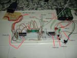
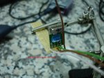
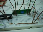
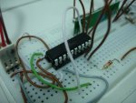
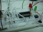
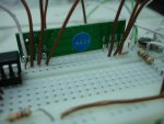
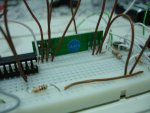
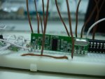
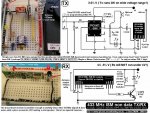
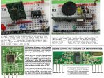
I bought this transmitter and this receiver and with a 18x Picaxe I want to send data (serout) to a 20x2 Picaxe (serin).

This is the code for 18x
Code:
#No_Data

main:


	for b0 = 1 to 10
		
		'-blink led to see when serout will be executed
		high 3

		
		serout 2,N1200,(85,85,85,85,"ABC","H")	
			
		
		low 3
		
		
		pause 200
		
		
	next b0
	

		pause 3000


goto main

and this is the code for 20x2

Code:
#No_Data


'--PortB as output
let dirsb = %11111111

symbol tab = 9


main:

	serin C.2, N1200,("ABC"),b1


	sertxd ("Result: ", tab, b1, CR, LF)


goto main

If I use i use a wire between the two picaxes everithing is ok and it works 100%, but when I switch to the transmitter (18x) and the receiver (20x2) nothing happens.

Is there any way that i can use to see if it a transmitter or a receiver problem?


Thank you
 

kd5crs

Senior Member
Here is a link to a project where I used these same things. Code is included. To be brief, you are running into the noise/autoranging wireless issue that everyone runs into with these modules.

Look for the lines that mention "Wolfgang" in the comments, and copy and paste. The theory is to send a bunch of "U"s (U is 10101010, I think) which conditions the receiver prior to the actual data.

http://www.picaxeforum.co.uk/showthread.php?t=14587

Brian
 

hugoxp1

Member
Here is a link to a project where I used these same things. Code is included. To be brief, you are running into the noise/autoranging wireless issue that everyone runs into with these modules.

Look for the lines that mention "Wolfgang" in the comments, and copy and paste. The theory is to send a bunch of "U"s (U is 10101010, I think) which conditions the receiver prior to the actual data.

http://www.picaxeforum.co.uk/showthread.php?t=14587

Brian

Hi Brian, thank you for your help... but still not working

I made this changes:

18x Code:

Code:
#No_Data


main:


	for b0 = 1 to 10
		
		'-blink led to see when serout will be executed
		high 3
		
			
		pause 10
		serout 2,N1200,(0x55,0x55,0x55,0x55,0x55,0x55,0x55,0x55,0x55,0x55)
		pause 5 

		serout 2,N1200,("ABC","U","H")	
		pause 5
		pause 10

		
		low 3
		
	
		pause 200
		
		
	next b0
	

	pause 3000

goto main

and for 20x2:

Code:
#No_Data

'--PortB as output
let dirsb = %11111111

symbol tab = 9


main:

	serin C.2, N1200,("ABC"),b0,b1


	sertxd ("Result: ", tab, b1, CR, LF)


goto main
I can't figure out what's wrong... :(
 

hugoxp1

Member
Images 1 and 2

I already tried with T1200 and with pause between the pre-amble and the data and I did not succeed :(


Well, i decided to attach the project images (because we are only able to insert 2 images for post I will upload the rest in mor two posts).

Thank you
 

Attachments

westaust55

Moderator
Well, i decided to attach the project images (because we are only able to insert 2 images for post I will upload the rest in mor two posts).
My solution to the 2 photo limit is to place a few photos into one jpg file using a "paint" type program.
 

westaust55

Moderator
A few thoughts:

1. In the receiving SERIN from the transmitter, try removing the qualifier "ABC" part and see if any data at all is getting through to the receiving end.

2. I would be looking to keep the general circuit wiring as short as possible. ALl those loops can act as antenae and disrupt the rest of the circuit.

3. How long are the antenna wires. Fom memory, they should be around 170mm long.
 

manuka

Senior Member
Those Sparkfun modules look akin to numerous similar "cheap 'n cheerful" 433 MHz data offerings. Suggest you initially test them as simply as possible - perhaps as below. Stan
 

Attachments

SAborn

Senior Member
Hi hugoxp1


I to had trouble getting data to TX and RX when i played with these modules originally.

A couple of things that might help you that i found was to send and receive the data in ascii format as this acts as a filter for all the crap rubbish you will also be picking up.

Example:-

serout TX ,T2400,($aa,$aa,#code,$aa,$aa,#1234567,$aa,$aa,#ABCDEF)

Example 2 :-

serin RX ,T2400,#code,#W1,#W2

In the examples the " $aa " is used as a wakeup to the RX and as a break between each block of data, Or the data will been seen as one string with no start/stop bits and will become corrupt.
You must have a block of non ascii data between each block of ascii data you send.

The $aa will be ignored by the receiving picaxe as it is not ASCII and the serin command calls for the data to be ASCII ( ASCII = " # " )

Using ascii for me was the difference between a useless set of junk and a system that worked reliabally over distance with very little corrupt data.

I think one is a fool not to use ascii in the data TX and RX, as it solves so many problems.

The second thing is the TX and RX boards might be too close when testing and if so one will swamp the other.
Try having them several meters apart and the antennes straight and vertical.

As also said before the breadboard wires can cause problems and breadboard is the worst sort of circuit board you can have for using wireless TX &RX modules.

Just send a known short block of data to start with till you can receive that, than expand the data you send to other stuff.

It is best to include a sertxt command in the receiving picaxe so it can write the data to the screen and use your F8 key to view it.

I find you get better response using T2400 compared to N2400.

Use a 1K resistor between the picaxe pin and the input to the TX module as i have killed a few picaxes with out it. (they work for a while and then one day they are dead and the TX too. No problems with the resistor in series)
 

hugoxp1

Member
Thank you all for your help.

I think I have some problem in my Rx or Tx, because I have tried all the things that you suggest and i don't have succeed :(

So, I will need to buy another pair of Tx/Rx... and that's why i opened another post.

Thank you all for your effort!

I will not stop until I put these two Picaxes communicating :)
 

kd5crs

Senior Member
These modules do work, I promise. I have 12 pairs of these things running in my house right now and for the last 2 months, reporting status once an hour, as well as every time someone wants to open a blind.

They are not simple to get working, though. Pretty much every post of mine is about these things, so I suggest searching for posts by me and working backwards. There were many breakthroughs in increasing reliability, so the latest posts should have them all.

Read this whole thread:

http://www.picaxeforum.co.uk/showthread.php?t=14334

As a bonus, it even has some interesting stuff about WWII antiaircraft shells at the end, because staying on topic is for :eek:

Brian
 

manuka

Senior Member
Use a 1K resistor between the picaxe pin and the input to the TX module as i have killed a few picaxes with out it.
I connect directly, & have never lost a PICAXE over the past 8 years (in ANY application!)

As also said before the breadboard wires can cause problems and breadboard is the worst sort of circuit board you can have for using wireless TX &RX modules.
I've made scores of VHF/UHF circuits directly to breadboard over the years with great success! While naturally alert to stray L & C issues,even compact discretes can work a treat - witness the 100 MHz FM Tx below. 433 MHz modules have all the RF on the small module anyway- only low speed digital & control signals dance around on the breadboard itself.

I agree about the RX/TX being too close- many pairs will be overwhelmed.

A UHF receiver can be one of the most useful aids when setting up at 433 MHz. If you can't borrow a scanner, then perhaps rustle up a dead simple receiver using a RX module. This makes a handy aid for general purpose 433 MHz Rx checks on wireless doorbells,car alarms,toys,backyard weather stations PLUS ( of course) allowing insights on general ISM nearby activity.

I again repeat - START VERY SIMPLY & verify things in stages. Stan.
 

Attachments

Last edited:

hugoxp1

Member
Finally...

Hi,

I am writing this post only to tell the end of this final "story" :)
and it is a good final.

the conclusion is: the first (and only pair) of Tx/Rx that I have bought don't "match"...I bought more two different pairs and after 30 seconds I put them communicating without single byte lost!

It's a "lot of pain" when you going to start something new with a hardware problem... well, at least I have learned a lot with your comments :)

THANK YOU ALL for your support!
 
Top