Serial Controller for KS0108B GLCD

nick12ab

Senior Member
I have completed the serial GLCD module stripboard edition. Firstly, I will say that all the oscillator problems were the fault of the breadboard as Hippy's ultra-fast serial testing program worked flawlessly at the speed which previously caused almost instant failure on the breadboard. Here are the pictures of the stripboard edition, which intentionally has the same footprint as the GLCD.

The solder side:

The trimmer pot is for adjustment of the contrast when using the GLCD's inverter instead of the on-board inverter. The inverter used is selected with a jumper on the other side.

The component side:

This side has an EEPROM socket which is currently unused and the on-board inverter which is covered with insulation tape to prevent it from shorting with anything on the back of the GLCD. The inverter selector jumper is just below the inverter. To connect the module to other things, I wanted to use terminal blocks but they were too tall and dodn't allow enough space for everything. A 10-way female header is used instead. Power and 0v have two connectors each to 'daisy-chain' it to another module (not that any others exist yet), serial in, busy out, execute in, reset. The last two connections are unused.

The completed thing:
 

MartinM57

Moderator
Good news and hopefully lessons learnt by all those involved in the thread.

What frequency resonator? Ideally it should be right next to the PICAXE pins.

So what about the EEPROM test program - does that work as expected now?
 

nick12ab

Senior Member
Good news and hopefully lessons learnt by all those involved in the thread.

What frequency resonator? Ideally it should be right next to the PICAXE pins.

So what about the EEPROM test program - does that work as expected now?
The resonator is less than two centimeters away from the PICAXE pins - on the stripboard wires have to be carefully placed in order to change the pin order of resonator-ground-resonator on the resonator to the ground-resonator-resonator order of the PICAXE. It is a 16MHz resonator.

The EEPROM test program - I want to run it now but the thing has decided it doesn't want to work and isn't responding to commands. Hippy's baudrate tester worked fine on the same module so it is probably a misplaced resistor on the Execute Now line so I'll investigate that now.
 

eclectic

Moderator
snip

The EEPROM test program - I want to run it now but the thing has decided it doesn't want to work and isn't responding to commands. Hippy's baudrate tester worked fine on the same module so it is probably a misplaced resistor on the Execute Now line so I'll investigate that now.
Just so any new folks are up to speed,
what is the EEPROM test program again?

e
 

nick12ab

Senior Member
Just so any new folks are up to speed,
what is the EEPROM test program again?

e
"The EEPROM test program is one that I made myself. It isn't very good for testing EEPROMs as although it clears and sets all bits for each byte before restoring the original value, it doesn't check inbetween, so stuck bits would pass undetected and the EEPROM would have to fail during the test for it to be detected. It is still ideal as a test for sending lots of data to the GLCD."

See post 72 for the code.

ADDED:
I ran this code sequence to check that it isn't the GLCD that's failed.
Code:
test:
	high rs
	pinsB = 0
	pulsout enablepin,1
	for loopcounter = 0 to 7
		pinsB = 1 << loopcounter
		pulsout enablepin,1
	next loopcounter
	return
In theory it should draw a short diagonal line. it does, but pixels on rows 2 and 4 are missing, so that could indicate that the data bus isn't connected to the PICAXE correctly but that shouldn't be stopping it from functioning.
 
Last edited:

eclectic

Moderator
=nick12ab;173258
snip
See post 72 for the code.
I've just looked at post #72.
Your codes (posted as .bas attachments)
have had
three views.

Just my opinion, but, would it be best to consolidate.

1. Post a new schematic.
2. Post code using [ code] [ /code ] tags.
There are several "watchers" here who seem to be lost.
Me first.
:-(

e
 

nick12ab

Senior Member
I've just looked at post #72.
Your codes (posted as .bas attachments)
have had
three views.

Just my opinion, but, would it be best to consolidate.

1. Post a new schematic.
2. Post code using [ code] [ /code ] tags.
There are several "watchers" here who seem to be lost.
Me first.
:-(

e
The 18M2 version:
Code:
#no_data
#no_end
#terminal off
#com 1
#picaxe 18M2

symbol buttonA = pinC.0
symbol buttonB = pinC.1
symbol busypin = pinC.5
symbol executenow = C.6
symbol pin = C.7
symbol readvar = b3
symbol addresscounter = w2
symbol readvar2 = b6
symbol progbarsize = b7
symbol errorcounter = w4
symbol aclsb = b4
symbol acmsb = b5

main:	pause 1000
	setfreq m32
	dirsA = $00
	dirsB = $44
	dirsC = $00
restarttest:
	serout pin,N19200_32,(246,0,192,1,247,192,0,248,0,192,0,253,0,"EEPROM TESTER v0.0",253,20,192,1,"Press A to start...",248,7)
	hi2csetup i2cmaster,%10100000,i2cfast_32,i2cbyte
wait1:if buttonA = 0 then wait1
x003:	if buttonA = 1 or buttonB = 1 then x003
	serout pin,N19200_32,(253,20,"Test in progress    ",253,40,"A=PAUSE     B=CANCEL",253,120,"Progress:",253,60,"Byte:",253,80,"Errors:",192,1,248,7)
	addresscounter = 0
test:
	inc addresscounter
		hi2cin addresscounter,(readvar)
		hi2cout addresscounter,(%10101010)
		pause 100
		hi2cout addresscounter,(%01010101)
		pause 100
		hi2cout addresscounter,(readvar)
		pause 100
		hi2cin addresscounter,(readvar2)
		progbarsize = addresscounter / 512
x004:		if busypin = 1 then x004
		serout pin,N19200_32,(253,66,#addresscounter,32,244,7,progbarsize)
		high executenow
x007:		if busypin = 0 then x007
		low executenow
		if readvar <> readvar2 then error
		if buttonA = 1 then paused
		if buttonB = 1 then cancel
resumey:
	if addresscounter > 0 then test
x008:	if busypin = 1 then x008
	serout pin,N19200_32,(192,1,247,192,0,253,0,"EEPROM TESTER v0.0",253,33)
	for addresscounter = 0 to 13
		lookup addresscounter,("TEST  COMPLETE"),readvar
		let readvar = readvar + 96
		serout pin,N19200_32,(readvar)
	next addresscounter
	serout pin,N19200_32,(253,140,"ERRORS: ",#errorcounter)
error:
	inc errorcounter
x006:		if busypin = 1 then x006
	serout pin,N19200_32,(253,80,"Errors: ",#errorcounter,32,253,100,"ERROR! ",#readvar," <> ",#readvar2,32,32,32)
paused:
x005:		if busypin = 1 then x005
x001:	if buttonA = 1 then x001
	serout pin,N19200_32,(253,20,"Test paused         ","A=CONTINUE")
x002:	if buttonA = 1 then resumex
	if buttonB = 1 then cancel
	goto x002

cancel:
	goto restarttest
	
resumex:
	if buttonA = 1 or buttonB = 1 or busypin = 1 then resumex
	serout pin,N19200_32,(246,0,253,20,"Test in progress    ",192,1,248,5)
	goto resumey
The PICAXE-20X2 version:
Code:
#no_table
#no_end
#terminal off
#com 1
#picaxe 20X2

symbol buttonA = pinb.4
symbol buttonB = pinb.3
symbol busypin = pinC.6
symbol executenow = B.2
symbol pin = B.6
symbol readvar = b3
symbol addresscounter = w2
symbol readvar2 = b6
symbol progbarsize = b7
symbol errorcounter = w4

main:	pause 1000
	setfreq m64
	dirsA = $00
	dirsB = $44
	dirsC = $00
restarttest:
	serout pin,N19200_64,(246,0,192,1,247,192,0,248,0,192,0,253,0,"EEPROM TESTER v0.0",253,20,192,1,"Press A to start...",248,7)
	hi2csetup i2cmaster,%10100000,i2cfast_64,i2cword
wait1:if buttonA = 0 then wait1
x003:	if buttonA = 1 or buttonB = 1 then x003
	serout pin,N19200_64,(253,20,"Test in progress    ",253,40,"A=PAUSE     B=CANCEL",253,120,"Progress:",253,60,"Byte:",253,80,"Errors:",192,1,248,7)
	addresscounter = 0
test:
	inc addresscounter
		hi2cin addresscounter,(readvar)
		hi2cout addresscounter,(%10101010)
		pause 100
		hi2cout addresscounter,(%01010101)
		pause 100
		hi2cout addresscounter,(readvar)
		pause 100
		hi2cin addresscounter,(readvar2)
		progbarsize = addresscounter >> 10
x004:		if busypin = 1 then x004
		serout pin,N19200_64,(253,66,#addresscounter,32,244,7,progbarsize)
		high executenow
x007:		if busypin = 0 then x007
		low executenow
		if readvar <> readvar2 then error
		if buttonA = 1 then paused
		if buttonB = 1 then cancel
resumey:
	if addresscounter > 0 then test
x008:	if busypin = 1 then x008
	serout pin,N19200_64,(192,1,247,192,0,253,0,"EEPROM TESTER v0.0",253,33)
	for addresscounter = 0 to 13
		lookup addresscounter,("TEST  COMPLETE"),readvar
		let readvar = readvar + 96
		serout pin,N19200_64,(readvar)
	next addresscounter
	serout pin,N19200_64,(253,140,"ERRORS: ",#errorcounter)
error:
	inc errorcounter
x006:		if busypin = 1 then x006
	serout pin,N19200_64,(253,80,"Errors: ",#errorcounter,32,253,100,"ERROR! ",#readvar," <> ",#readvar2,32,32,32)
paused:
x005:		if busypin = 1 then x005
x001:	if buttonA = 1 then x001
	serout pin,N19200_64,(253,20,"Test paused         ","A=CONTINUE")
x002:	if buttonA = 1 then resumex
	if buttonB = 1 then cancel
	goto x002

cancel:
	goto restarttest
	
resumex:
	if buttonA = 1 or buttonB = 1 or busypin = 1 then resumex
	serout pin,N19200_64,(246,0,253,20,"Test in progress    ",192,1,248,5)
	goto resumey
For the schematic, do you just want it attached again like it is or converted into an image file or do you want something to be improved on?
 

nick12ab

Senior Member
Ah! I feel so stupid now! The reason why it wasn't working temporarily was because I used N19200_64 instead of B19200_64 with the hsersetup command and those constants are different. It works now.

The missing pixels were caused by an insufficiently cut stripboard track.

ADDED:

I have connected the simple tester (18M2) back up to the GLCD and unlike before, this time it will display "GLCD DRIVER TEST" and "00000" on the display but it (18M2) then instantly resets itself as the screen briefly blanks as it's part of the startup routine of the code. I have tried simulating the code and it works fine.
Code:
#picaxe 18M2
#terminal off
#no_data
symbol counter = w2
symbol buttonA = pinC.0
symbol buttonB = pinC.1
symbol busy = pinC.5
symbol executenow = C.6
symbol pin = C.7
main:
	wait 2
	output pin
	output executenow
	setfreq m32
	serout pin,N19200_32,(192,1,247,246,0,249,255,253,0,"GLCD DRIVER TESTER")
loopthing:
	bintoascii counter,b6,b7,b8,b9,b10
	b6 = b6 + 96
	b7 = b7 + 96
	b8 = b8 + 96
	b9 = b9 + 96
	b10 = b10 + 96
	serout pin,N19200_32,(253,16,32,32,32,b6,b7,b8,b9,b10)
	high executenow
wait01:
	if busy = 0 then wait01
	low executenow
wait02:
	if busy = 1 then wait02
	inc counter
	goto loopthing
 
Last edited:

nick12ab

Senior Member
Winstar LEDs and OLEDs

IT'S A MIRACLE!!!!

Rapid have resumed selling the Winstar range of OLEDs and LCDs! Go there now!

This time there are actually product images so hopefully they won't disappear again.

They even have 128x64 graphic LCDs with RGB backlights!

Unfortunately the graphic OLEDs have awkward ribbon cable connectors and are much more expensive than the LCD variant.
 
Last edited:

nick12ab

Senior Member
Any ideas why the 18M2 which is testing the driver is resetting? I tried inserting various 'it got here' sertxds and it stopped immediately before the execute now line goes high - but disconnecting the execute now line does nothing and a multimeter shows that there is no short circuit between the busy pin and a power rail.
 

hippy

Ex-Staff (retired)
Staff member
Any ideas why the 18M2 which is testing the driver is resetting? I tried inserting various 'it got here' sertxds and it stopped immediately before the execute now line goes high - but disconnecting the execute now line does nothing and a multimeter shows that there is no short circuit between the busy pin and a power rail.
So it resets after the SEROUT ? Perhaps that points to where a short is ?

Or perhaps it's not the 18M2 but the 28X2 driver, receiving data and doing something which in turn causes the 18M2 to reset ? Maybe the 28X2 has a short somewhere or perhaps each PICAXE is ending up with two outputs colliding when one side should be an input ?

Perhaps it's got something to do with I2C or perhaps something else not shown on your circuit ?

The best approach I can suggest is simplifying your test code, extend that a step at a time towards what you finally want, see where it falls to pieces and hope that whatever you last added gives a good clue as to what is going wrong.

Definitely cut the I2C stuff from the 18M2, the GLCD handling from the 28X2, just get the comms protocol working first. To more easily find what's going wrong you need to reproduce it with the simplest steps without any distractions which cloud analysis.
 

nick12ab

Senior Member
So it resets after the SEROUT ? Perhaps that points to where a short is ?

Or perhaps it's not the 18M2 but the 28X2 driver, receiving data and doing something which in turn causes the 18M2 to reset ? Maybe the 28X2 has a short somewhere or perhaps each PICAXE is ending up with two outputs colliding when one side should be an input ?

Perhaps it's got something to do with I2C or perhaps something else not shown on your circuit ?

The best approach I can suggest is simplifying your test code, extend that a step at a time towards what you finally want, see where it falls to pieces and hope that whatever you last added gives a good clue as to what is going wrong.

Definitely cut the I2C stuff from the 18M2, the GLCD handling from the 28X2, just get the comms protocol working first. To more easily find what's going wrong you need to reproduce it with the simplest steps without any distractions which cloud analysis.
The 18M2 and 40X2 didn't have any i2c stuff. When remiving all of the busy checking from the test program, the counter would get to around 5, maybe more before it restarted. The computer can interface fine with the GLCD driver. I switched to a 40X2 and it got much further before freezing so it is somewhat related to the chip. I connect the 40X2 directly to the computer and the terminal reveals that it's working correctly as long as the GLCD driver chip isn't connected. Pressing the reset button on the GLCD driver causes the counter to advance by one. If the data is being sent to the driver and the sending PICAXE freezes, pressing the Reset button on the GLCD driver causes it to resume so there must be something in the code of the GLCD driver that is causing the busy pin to not go low etc. which I will look for. There is also occasional corruption.

EDIT: Well it turns out that the GLCD was executing the commands too quickly for the controlling PICAXE to detect the busy signal and therefore it got stuck in that first loop for an eternity. Adding a timeout fixed that. Now back to the return of the dreaded corruption - going to run Hippy's test program again.
 
Last edited:

MartinM57

Moderator
If I was a user of your GLCD driver I would ideally want to be able to treat it just like an external device
- fire a set of ascii codes at it
- expect it to buffer a reasonable number of characters (128/256)
- expect it to be able to keep up with me (with you telling me what limitations I need to keep within e.g. wait 10ms or whatever between blocks of commands)

At the worst I would deal with a busy line back from the driver.

I wouldn't want to have to send commands, tell it to execute by raising another line, and watch a busy line before continuing - it's too complex - as you have seen.
 

nick12ab

Senior Member
If I was a user of your GLCD driver I would ideally want to be able to treat it just like an external device
- fire a set of ascii codes at it
- expect it to buffer a reasonable number of characters (128/256)
- expect it to be able to keep up with me (with you telling me what limitations I need to keep within e.g. wait 10ms or whatever between blocks of commands)

At the worst I would deal with a busy line back from the driver.

I wouldn't want to have to send commands, tell it to execute by raising another line, and watch a busy line before continuing - it's too complex - as you have seen.
The execution line is an option and is sort of an experiment. It is not required to use it nor is the busy line. The buffer is 1024. Not using the execution line is just like using any driver where it waits for a pause in transmissions.
 

nick12ab

Senior Member
I have retried Hippy's test code and it works perfectly at the high speed.

There is still corruption when using the slower baud rate and the GLCD. When using the fast baud rate as used in Hippy's experiment, the corruption was the same. Is there any possibility that the PWM interferes with the hardware serial?

ADDED: It appears that the corruption is not timing related but is the first one or two bytes being dropped off causing the location to be not set and characters to be printed in the wrong place or the box drawing at address 16 to be printed below the 'L' in 'GLCD DRIVER TESTER' on the GLCD as 16 is a number used as the character location to print the loop counter.
 
Last edited:

nick12ab

Senior Member
I have tried removing all PWMs from the code and the hardware serial still drops off the first few bytes occasionally and I've tried multiple different power supplies including AC adaptors and AA batteries with still no success.
hippy said:
Note that one fail may cause subsequent cascade fails but should catch up and be okay from then on.
This would mean that hippy's test code is immune from the problem except for it saying FAIL once or twice on startup then followed by the dashes.

This is an example of what the GLCD looks like after running for a short while:

Yes, I know eclectic and hippy recommend that images should be attached rather than embedded but the picture's so small anyway that the attached thumbnails group would be no smaller than the image itself and the image is only 1.18KB.

I'm using hserout on the 18M2 currently, so does the pin stay in the correct state (low) after it has transmitted the data?

EDIT: Now saved the example in .GIF format which reduced the file size down to 413 bytes with no visual change at all.
 
Last edited:

hippy

Ex-Staff (retired)
Staff member
It does sound like something is going wrong in the way you are receiving the data. I recall you were using HSERSETUP OFF in your early code - not sure if or how that would affect things but it's usually best to enable background receive and leave it enabled. HSEROUT will leave the output signal as it was ( assuming you aren't also using HSERSETUP OFF in the sender ). It could be that your handshaking method is causing some problems.

As noted previously it's a complicated mechanism you have for buffering receive data and there could be timing issues with it; complicated = difficult to analyse = difficult to debug = difficult to say if flawed or not.
 

nick12ab

Senior Member
it's usually best to enable background receive and leave it enabled.
I am considering modifying the code for that. First, is there a background delay after executing the hsersetup command before it will actually receive something?
 

hippy

Ex-Staff (retired)
Staff member
No delay that I know of. Once the HSERSETUP command completes the relevant SFR's will have been set and it should be ready to receive any data sent to it.

But that did make me notice that you don't have pull-ups or pull-downs on the busy and execute lines, so you cannot guarantee how the reading PICAXE will see them if the asserting PICAXE hasn't made those outputs at the time it looks. You could see odd things happen when either resets, during or immediately after download, if the other is relying on those signals to be correct. For example, the 18M2 may think it's received a not-busy signal before the 28X2 is ready, the 28X2 may see an execute before anything has been sent.
 

nick12ab

Senior Member
But that did make me notice that you don't have pull-ups or pull-downs on the busy and execute lines, so you cannot guarantee how the reading PICAXE will see them if the asserting PICAXE hasn't made those outputs at the time it looks.
On the stripboard mdule, the serial in and execute now lines have pull downs and the busy and reset lines have pull-up resistors.
 

nick12ab

Senior Member
I have removed the 'hsersetup off' command from the GLCD driver code and moved the 'hsersetup 7,%00111' so that it is only executed once. There is no longer a box drawing like before but the second number still appears occasionally, but with no space inbetween it and the previous number.

Example:


Yes, this is an exact drawing of what appeared on the GLCD.
 
Last edited:

nick12ab

Senior Member
Winstar LCDs and OLEDs

Some LCDs and OLEDs from Rapid's LCD Range have been discontinued AGAIN! Discontinued products include the 128x64 GLCDs! - and also 8x2 OLEDs. Again it seems to be all those without pictures except the 16x1 OLEDs. They'll probably be back next month.

I've also got a question for those more experienced with LCDs and backlights: I want to have an LCD which is both sunlight readable (i.e. not transmissive) and the backlight is low power (i.e. edge light rather than matrix panel) but the only options (for 16x2 large character) are no backlight reflective, matrix backlight transflective and edge light transmissive (the edge light actually being LEDs mounted at the edge of a plastic panel) so can I mount white LEDs at the edge of the LCD panel itself on the reflective no backlight version and make the display readable with the LEDs on and no other external light?
 

nick12ab

Senior Member
can I mount white LEDs at the edge of the LCD panel itself on the reflective no backlight version and make the display readable with the LEDs on and no other external light?
no i can't - it only makes the lit edge glow dimly and is pathetic.
 

nick12ab

Senior Member
Byte dropping fixed!

The problem where the first one or two bytes get dropped is fixed. I increased the timeout in the section of code in the tester and there is now no problem.
Code:
#picaxe 18M2
#terminal off
#no_data
symbol counter = w2
symbol buttonA = pinC.0
symbol buttonB = pinC.1
symbol busy = pinC.5
symbol executenow = C.6
symbol pin = C.7
main:
	wait 2
	output pin
	output executenow
	setfreq m32
	HSerSetup B19200_32, %010
	hserout 0,(0,192,1,247,246,0,249,255,253,0,"GLCD DRIVER TESTER")
loopthing:
	bintoascii counter,b6,b7,b8,b9,b10
	b6 = b6 + 96
	b7 = b7 + 96
	b8 = b8 + 96
	b9 = b9 + 96
	b10 = b10 + 96
	hserout 0,(0,253,16,b6,b7,b8,b9,b10)
	high executenow
	time = 0
	do until busy = 1 or time > 1 : loop
	low executenow
	time = 0
	do until busy = 0 or time > 1 : loop
	inc counter
	goto loopthing
For backlight improvement, using a different colour LED (like orange) massively enhances the viewing area but I only have one LED so it's too dim. A red or orange sweet wrapper in between the LCD and the backlight panel might be the way to go.
 

nick12ab

Senior Member
Big question now... WHY WHY WHY did the designers make the PICAXE system an interpreter based system and not just a bootloader-based system? If the software claims it can convert BASIC to Assembler, then they could have been capable of just having a bootloader that can download the compiled code if download is pressed before applying power to the PICAXE and then execute the code like a normal PIC. Maybe meLabs paid Rev-Ed to not do that because their massively overpriced PicBASIC compiler would no longer get any sales.
I think I've worked out why they did this - the BASIC compiler in P.E. is awful so wouldn't be useable with PICAXE and if they made it better for use with a bootloader system, because it would be a basic-to-assembler compiler and someone will be able to get the assembled code by using another COM port to echo what's being programmed onto the chip and then a non-PICAXE can be programmed with it.
 

nick12ab

Senior Member
Character Set Opinions please

Now that there isn't much more tweaking that can be done on the text without starving it of features (inversion), I'm going to do a bit of touching up of the character set. Characters are commonly disputed between manufacturers as each different manufacturer you use will be using some sort of variation. These are some characters that can be different with the current character in my set on top and an alternative below each one:


For each character, which variant do you prefer?
 
Last edited:

westaust55

Moderator
I think I've worked out why they did this - the BASIC compiler in P.E. is awful so wouldn't be useable with PICAXE and if they made it better for use with a bootloader system, because it would be a basic-to-assembler compiler.
@nick12ab,
The PICAXE system is not awful as you state, it is a need for you to align your expectations.

The method used by the PiCAXE is the same as use by the BasicStamp and many past home computers such as the C-64.
With this method of programming the user types in an English-like language and this is tokenized and stored as such for the interpreter to read and perform the assembler functions / instructions to provide the actions the user desires.
Rev Ed provide this programming environment for FREE.

If you want a compiler based environment, then you need to select a suitable micro and a suitable compiler. The micro may cost no more but you will likely pay for any good full featured BASIC to assembler compiler software package.
 

westaust55

Moderator
For each character, which variant do you prefer?
Personal preference is to have the top of lowercase characters at the same height.
I can accept the uppercase "A" eitherway.
Where the opportunity exists, my preference (which is what you are seeking?) is to have real descenders for those characters such as g j p q y
 

nick12ab

Senior Member
The PICAXE system is not awful as you state, it is a need for you to align your expectations.
I stated that the BASIC [highlight]compiler[/highlight] is awful, not the PICAXE system which uses a BASIC [highlight]tokeniser thing[/highlight]. The BASIC compiler being the one for the 'PIC-Logicator' branded programmer where you have to pay extra if you want it in a case! What I'm saying is that if they used a bootloader on the PICAXE and had a decent BASIC compiler instead of [highlight]a tokeniser[/highlight], someone could intercept the download and dump it to a hex file for programming onto a normal PIC and they'd have a free BASIC compiler, which Rev-Ed doesn't want to do as they have to make money from the PICAXE system in order to survive as a business.

And since true descenders are quite wanted, I'll use a bit of the settings byte to choose from the true descender font and the non-descender font in case the user's application results in characters growing out of each other with the true descenders.
 

westaust55

Moderator
I stated that the BASIC [highlight]compiler[/highlight] is awful, not the PICAXE system which uses a BASIC [highlight]tokeniser thing[/highlight]. The BASIC compiler being the one for the 'PIC-Logicator' branded programmer where you have to pay extra if you want it in a case!
Hmm, I must be confused, as I read "the BASIC compiler in P.E. is awful " and saw no reference to the 'PIC-Logicator'

And since true descenders are quite wanted, I'll use a bit of the settings byte to choose from the true descender font and the non-descender font in case the user's application results in characters growing out of each other with the true descenders.
Seems like a good idea. :)
 

nick12ab

Senior Member
Hmm, I must be confused, as I read "the BASIC compiler in P.E. is awful " and saw no reference to the 'PIC-Logicator'
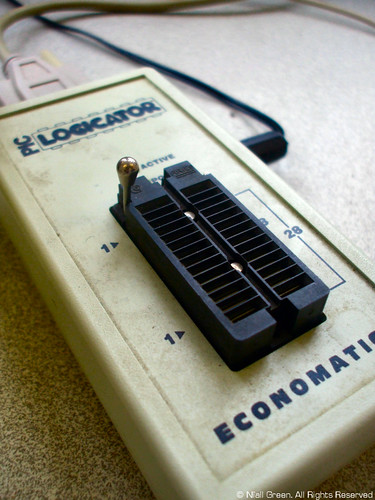
The 'PIC-Logicator' is the BAS800C which I've seen with the PIC-Logicator logo printed on its case. This programmer is a cased version of BAS800 and is the one required to use the BASIC compiler in P.E.

Stolen image:

 
Last edited:

westaust55

Moderator
Fair enough.

I have always taken the view that "Logicator" was software.
From the Rev Ed website:
The Logicator for PIC® and PICAXE® micros software is available as a single user shareware version for home/personal use, or as a site licence (any number of computers) for educational use (code LGC001 new site licence / code LGC002 upgrade from v1 or v2). Educational site licence holders may also choose to optionally purchase the 'home user add-on licence', which then allows students and teachers of the school to use the software at home (registered without further charge).

The software download will run in 'shareware mode' until a licence key is purchased and installed. The shareware version is not restricted in any way (apart from a nag screen), however if you use the software regularly you should register the software (£15, approx. $20).
‘Logicator for PIC® micros’ is the new name for ‘PIC-Logicator’ and is now developed, published and supplied directly by Revolution Education Ltd.
 

Attachments

Last edited:

hippy

Ex-Staff (retired)
Staff member
Hmm, I must be confused, as I read "the BASIC compiler in P.E. is awful " and saw no reference to the 'PIC-Logicator'
That confused me too but I let it pass.

It seems we are talking about the Basic to Assembler converter and BAS800 PIC programming combo, which is an educational tool so not really 'awful' but it is limited in functionality when compared to a commercial compiler.

When we normally talk of Basic Compiler for the PICAXE we usually mean the 'tokeniser'. There can be debate on what correct terminology could or should be but "compiler" is technically correct as the tokens output are the native instruction set of a PICAXE system.
 

srnet

Senior Member
Maybe meLabs paid Rev-Ed to not do that because their massively overpriced PicBASIC compiler would no longer get any sales
Very strange comment indeed.

At £169 the PicBasic Compiler, would from a commercial users perspective, be outstanding value, an insignificant cost really.

I have bought the Mikrobasic Pro Compiler (£129) and for what it can do I consider it very good value for a bit of software.
 

nick12ab

Senior Member
At £169 the PicBasic Compiler, would from a commercial users perspective, be outstanding value, an insignificant cost really.
I'm not a commercial user (yet) so it is expensive but even for commercial use a company would rather pay nothing for a decent compiler rather than pay for it providing the pay nothing option is legal.

If you use MikroBasic, how similar is it to PICAXE Basic?
 

westaust55

Moderator
If you use MikroBasic, how similar is it to PICAXE Basic?
While I have had a look, I have not used the MikroBASIC compiler (for BASIC to assembler).

Have a look here: http://www.mikroe.com/eng/products/view/9/mikrobasic-pro-for-pic/

There are many derivatives/flavours of BASIC to take into account the capabilities of the destination chips. It is only the fundamental structures that are nominally the same.
While you could port a PICAXE program it would not be a "drop in" situation and would require your doing some work.

What are you trying to do/undertake that you wish to consider such alternatives to the FREE Revolution Education BASIC programming Editor environment?
 

srnet

Senior Member
If you use MikroBasic, how similar is it to PICAXE Basic?
Very different, you really need to be able to know how to manipulate PIC registers directly to achieve some things that a PICAXE will do for you. There are standard libraries of course, that allow you to write for I2C, SPI, Compact flash, LCD, Ethernet and many more. Its faster, does floating point, trig, procedures, modular programs and the like.

But PICAXE fulfills its role very well, MUCH easier development and very cheap.

One of the best features of PICAXE however is the ease to which it becomes involved in schools. For smaller PICS (up to 4K flash code) Mikrobasic is free to use, but it would be a complete non-starter (in my view) for educational use, too complex and error prone (by the user). My own son, 15, has already done a couple of simple PICAXE projects as part of a GCSE Systems.
 

srnet

Senior Member
Oh and another thing, the 'FREE' support you get in here is excellant.

Mikcrobasic support is pants.
 
Top