Scanning 4 out of 8 Input Pins on 28X1

Dear All

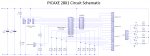
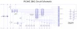
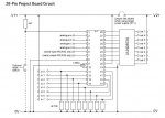
I am using a PICAXE 28X1 and like to be able to call different sub routines depending on what is on four out of the eight digital inputs.

I have a 4 bit binary number 0 - 15 (decimal equivilent) that I would like to feed into 4 of the digital inputs of the PICAXE. I would then like to use the different input "codes" to start different sub flows.

Any help would greatly appreciated. :)
 

Jeremy Leach

Senior Member
Hello, sounds like the 'On...Gosub' command might be what you need. Have a read up in manual 2. This enables you to gosub different routines depending on the value of a variable. This and the Branch command can be very handy ;)
 

westaust55

Moderator
try some code like this:

Code:
main:
let b1 = pins
b1 = b1 AND $0F
ON b1 GOSUB lab0, lab1, lab2, lab3, lab4,   . . .    , lab15
GOTO main

lab0:
; do something
return

lab1:

;
; etc
;
 
Okay... I think I am getting that. Thanks! :) The lab things can be changed to anything can they not? So I could use say code0 code1 code2 etc.? Also I don't understand what the "b1 = b1 AND $0F" is for.

Does this ensure that variable b1 can only be 15 or less? As there may be other inputs that I use and so I don't want it to scan these inputs before it is in a sub routine.
 

westaust55

Moderator
Yes lab0, lab1 etc are just sample label names. You can use whatever label names you wish within the PICAXE BASIC rules (see manual 2 = no command keywords and none of the keywords listed on page 194).

The b1 = b1 AND $0F (or b1 = b1 AND 15) is a mask so only the lowest 4 pins 0, 1, 2 and 3 are considered and the result is a value between 0 and 15.
 
Last edited:

tiscando

Senior Member
When I had a problem in a picaxe program with picaxe VSM, a month later, I found out that in a picaxe program, there were more than 255 gosubs (for 28x1), with all the uncounted ones inside the on...gosub!:eek: This means that neither PE's complier nor AXEVSM1.dll in VSM counts the gosubs inside the on...gosub. Could anyone look into this?
If the on...gosub doesn't really need to be counted so it works in real picaxes, than that VSM code problem may only be caused by that chasing fault to do with program flow (and not to do with one particular command) that has been chasing and ann:mad:ying me all the time!

see: :(so many axevsm errors that don't error on the programming editor, with that chasing fault being the most abdundant. :p

@wa55 and hwa04 above - Or b1 = b1 AND %00001111
 
Last edited:

hippy

Ex-Staff (retired)
I cannot comment on the VSM side of things but, while the ON-GOSUB does generate multiple GOSUB tokens, because of the way the command is tokenised they only count as one GOSUB in total.
 

Technical

Technical Support
Staff member
VSM, AXEpad and Programming Editor all use exactly the same compilers, so on...gosub counts as one gosub in all cases.
 
A Big THANK YOU :)

Ok... first of all a big thank you to everyone that has helped me! It has really been appreciated.

But I have a few more questions, so I will post my code and explain below:

Code:
main:
let b1 = pins
b1 = b1 AND %1111
ON b1 GOSUB lab0, lab1, lab2, lab3, lab4, lab5, lab6, lab7, lab8, lab9, lab10, lab11, lab12, lab13, lab14, lab15
GOTO main

lab0:
let pins = 15
return

lab1:
let pins = 14
return

lab2:
let pins = 13
return

lab3:
let pins = 12
return

lab4:
let pins = 11
return

lab5:
let pins = 10
return

lab6:
let pins = 9
return

lab7:
let pins = 8
return

lab8:
let pins = 7
return

lab9:
let pins = 6
return

lab10:
let pins = 5
return

lab11:
let pins = 4
return

lab12:
let pins = 3
return

lab13:
let pins = 2
return

lab14:
let pins = 1
return

lab15:
let pins = 0
return
As you can see from my code above... I have changed the mask thing to %1111 because the hexadecimal was just confusing me! :)

But I have a few problems... I have to have it 15 to 0 on the sub routines and not 0 - 15 for some bizarre reason, otherwise the LEDs that I am using for indication work in the opposite way? :S

And the only way to stop it displaying 16 when there is no signal on the inputs is to put "let pins = 256" into the first go sub.

Also the very last sub routine doesn't work. No matter what I put into it, it just won't do anything. Any help would be greatly appreciated.
 

lbenson

Senior Member
I can't speak to your last question, but if your real subroutines don't do anything more than what is shown, then you don't need the gosubs at all. In each case pins is set to 15 minus the value of b1, so you could just do the following:

#picaxe 28x1

main:
let b1 = pins
b1 = b1 AND %1111 ' zero-out most significant 4 bits.
b1 = 15 - b1
pins = b1
goto main

No subroutines required at all. Try it in the simulator and see if it does what you want.
 
Sorry... didn't explain myself properly. My project consists of a transmitter and receiver, one a code is received it is fed into the PICAXE and I would like it to do different things with different button presses. The let pins commands are just to test that the subs are working properly.
 

lbenson

Senior Member
You could also use the "select case" set of statements. I don't know how it would compare with "on gosub" as far as code space or execution time go, but to me it makes for a cleaner structure. YMMV
 

westaust55

Moderator
Ok... first of all a big thank you to everyone that has helped me! It has really been appreciated.


But I have a few problems... I have to have it 15 to 0 on the sub routines and not 0 - 15 for some bizarre reason, otherwise the LEDs that I am using for indication work in the opposite way? :S

Any help would be greatly appreciated.
How do you have the LED's connected. See the attached diagram.
That will influenence whether the PICAXE 28X1 output is high or low for the LED to be On.
 

Attachments

Last edited:

westaust55

Moderator
Ok... first of all a big thank you to everyone that has helped me! It has really been appreciated.

But I have a few more questions, so I will post my code and explain below:
:
:
:
Also the very last sub routine doesn't work. No matter what I put into it, it just won't do anything. Any help would be greatly appreciated.

Are you expecting an LED to illuminate.
Depends how you have the LED's conencted to the PICAXE.
All the outputs are in the OFF/LOW state and will sink current at the Lab15: subroutine.
 

hippy

Ex-Staff (retired)
But I have a few problems... I have to have it 15 to 0 on the sub routines and not 0 - 15 for some bizarre reason, otherwise the LEDs that I am using for indication work in the opposite way? :S
This could be an inversion issue with your inputs, in which case inverting them when you read them should solve that ...

b1 = pins & %1111 ^ %1111
 
Thanks the inverting thing seemed to do the trick, but is there any way of doing it just by wiring them up differently? I have wired them so that there is a resistor on the output and this connects to the cathode of the LEDs. The anodes are then commoned and connected to the posistive of the battery.

I still can't get it to display 0 when the input is 0. It just seems to display 15 all of the time unless you press another button. This means that I can't tell if 15 is working correctly. So I decided to set lab15 to let pins = 20 and this changed what was displayed when there was no input. So it seems that whatever lab15 is set to is what is displayed when the input is 0.

HTH, I just can't understand it. :(
 

westaust55

Moderator
If the inputs are all zeros and you have inverted the status of the bits as others have suggested then %xxxx0000 becomes %xxx1111 = 15


Did you look at the attachement I provided in an earlier post (post 13)?

How about uploading your circuit diagram (schematic) so we can see what you are doing in hardware.
 
Yes I did, unfortunately I didn't realise that the LEDs stayed the same way round though! DOH! will give it a go now. :) I will try and post a circuit diagram if I can, presumably the invert then isn't needed. Also do I need to use an 8 bit binary number or can I just get away with using the 4 bit one?

EDIT: This doesn't work at all for some reason. :( Will make a circuit diagram now and post ASAP.
 
Last edited:
Okay... here is a circuit diagram, its the best I can do, but should show what I mean. CN9 would be connected to outputs 0 - 3. Then inputs 0 - 3 have the code the the receiver is sending it.

Please see attached picture. Sorry for the size, I couldn't get it any smaller without it loosing quality.
 

Attachments

lbenson

Senior Member
This is probably a drawing error and not a wiring error, but leg 8 on the 28X1 should connect to 0V, not to the programming connector serial input signal.
 

westaust55

Moderator
Okay... here is a circuit diagram, its the best I can do, but should show what I mean. CN9 would be connected to outputs 0 - 3. Then inputs 0 - 3 have the code the the receiver is sending it.

Please see attached picture. Sorry for the size, I couldn't get it any smaller without it loosing quality.

Ah it become more clear now (well maybe).

You have a ULN2803 8 channel Darlington Driver IC conencted to the PICAXE outputs.

The Darlington transistors are tied to ground and so can only pull the output down toward ground and effectively sink current.

I presume you are conencting the LED's to the outputs of the ULN2803.

In this case, they must be wired as per your diagram to the connector CN3 and that connector wired to the "OUTPUTS 0-3 connector"

They will not work with the LED's connected to 0V as per the bottom part of my diagram.

The alternative is to wire the LED's directly to the PICAXE output pins if the board has provision (holes) to do that.
 
Last edited:
Sorry, my mistake again... On the diagram I posted, the LEDs should be that way round but connected to ground not +ive. It works this way but not properly without inverting the input. I still can't get it to do let pins = 0 either for some reason in the lab0.
 

westaust55

Moderator
LED via ULN2803

The inversion is not occuring within the PIACXE chip but is a funciton of the ULN2803.

If you look at the attached diagram.

If an input goes HIGH and you make the corresponding output follow, then the output will go HIGH,
then the ULN2803 input is HIGH which will turn on the transistors.
The Darlington transistor output pin is pulled LOW so the LED will only light IF it is wire the right way around
 

Attachments

westaust55

Moderator
Sorry, my mistake again... On the diagram I posted, the LEDs should be that way round but connected to ground not +ive. It works this way but not properly without inverting the input. I still can't get it to do let pins = 0 either for some reason in the lab0.
Now in post 9 you say the last subroutine does not work.
But it may be doing the right thing . . .

Lets look at some of the other cases (note that LED0 relates to the least significant bit which is on the right when we look at the 8 bits for a byte).

At Lab0: you have pins = 15 => pins = %00001111 so each ULN2803 is made high and the 4 LED’s come on

At Lab1: you have pins = 14 => pins = %00001110 so LED’s 1,2,3 come on and Led 0 is off

At Lab5: you have pins = 10 => pins = $00001010 so LED’s 1 and 2 come on and LEDs 0 and 3 are off.

When you get to the last routine
At Lab 15: you have pins = 0 => pins = $00000000 so no LED’s will come on.


In your last post, after you have added inversion you have made Lab0: pins = 0 but still the same thing, that is pins = 0 so no PICAXE outputs are on/high.

So as I see it pins = 0 is not going to make any LED's light up.

I trust that this might clarify things as to how it should operate.
 
Okay, I have downloaded the new program now. And it works. Well sort of. I have the inverter thing in the program: "%00001111 ^ %00001111". However I can't get it to display 00000000. It seems that whatever is set to display in lab15 displays not only when there is 15 input but also when 0 is input.
 

hippy

Ex-Staff (retired)
@ holmedwa04 : Can you post an up to date circuit diagram and the program code you are using. Could you also show how the buttons ( or whatever ) connect to the inputs, whether pull-up or pull down. Multiple inversions, both software and hardware, can make things get complex very quickly.
 
Okay, as requested an up to date diagram and code:

Code:
main:
let b1 = pins
b1 = b1 & %00001111 ^ %00001111
ON b1 GOSUB lab0, lab1, lab2, lab3, lab4, lab5, lab6, lab7, lab8, lab9, lab10, lab11, lab12, lab13, lab14, lab15
GOTO main

lab0:
let pins = %00000000
return

lab1:
let pins = %00000001
return

lab2:
let pins = %00000010
return

lab3:
let pins = %00000011
return

lab4:
let pins = %00000100
return

lab5:
let pins = %00000101
return

lab6:
let pins = %00000110
return

lab7:
let pins = %00000111
return

lab8:
let pins = %00001000
return

lab9:
let pins = %00001001
return

lab10:
let pins = %00001010
return

lab11:
let pins = %00001011
return

lab12:
let pins = %00001100
return

lab13:
let pins = %00001101
return

lab14:
let pins = %00001110
return

lab15:
let pins = %10101010
return
Please see attachment for circuit diagram. I am positive these are exactly how they are wired and that the code is definitely this now.

As for the other bits... I have a 4 x 4 keypad of which the outputs are encoded into binary and fed into an encoder ready to be transmitted. Once transmitted they are received and decoded back to binary. It is this binary that is being input into inputs 0 - 3 of the PICAXE.

HTH
 

Attachments

hippy

Ex-Staff (retired)
Thanks, so .... with all inputs disconnected ...

The pull-downs will pull the input pins to 0V
These will read as %00000000
The masking and inversion will make these %1111, stored in b1, value 15
ON-GOSUB with b1=15 should jump to lab15
lab15 sets pins=%10101010
The outputs of pins will be HLHLHLHL
The ULN2803 inverts so its outputs will be LHLHLHLH
LED's light when the ULN2803 outputs are low, so *-*-*-*-
LED's 0, 2, 4 and 6 are off, LED's 1, 3, 5 and 7 on

Is that what you are seeing ?
 
Last edited:

eclectic

Moderator
Okay, as requested an up to date diagram and code:

Code:
main:
let b1 = pins
b1 = b1 & %00001111 ^ %00001111
ON b1 GOSUB lab0, lab1, lab2, lab3, lab4, lab5, lab6, lab7, lab8, lab9, lab10, lab11, lab12, lab13, lab14, lab15
GOTO main

lab0:
let pins = %00000000
return

lab1:
let pins = %00000001
return

lab2:
let pins = %00000010
return

lab3:
let pins = %00000011
return

lab4:
let pins = %00000100
return

lab5:
let pins = %00000101
return

lab6:
let pins = %00000110
return

lab7:
let pins = %00000111
return

lab8:
let pins = %00001000
return

lab9:
let pins = %00001001
return

lab10:
let pins = %00001010
return

lab11:
let pins = %00001011
return

lab12:
let pins = %00001100
return

lab13:
let pins = %00001101
return

lab14:
let pins = %00001110
return

lab15:
let pins = %10101010
return
Please see attachment for circuit diagram. I am positive these are exactly how they are wired and that the code is definitely this now.

As for the other bits... I have a 4 x 4 keypad of which the outputs are encoded into binary and fed into an encoder ready to be transmitted. Once transmitted they are received and decoded back to binary. It is this binary that is being input into inputs 0 - 3 of the PICAXE.

HTH
@holmdwa
Following from hippy,

I've just built and tried part of this circuit.
A few things that might help ?

On your ULN2003, is Leg 9 connected to V+ ?

In your label lab15, don't you need ?
Code:
lab15:
let pins = %10101010

RETURN ; ******
Otherwise,
Code:
lab15:
;let pins = %10101010

let pins = %00001111
RETURN ; ******
will complete the list of input inversions.

e
 
This is probably a drawing error and not a wiring error, but leg 8 on the 28X1 should connect to 0V, not to the programming connector serial input signal.
Thanks... yes I think it is a drawing error. I only have the PCB foil to this and so I had to make the circuit diagram from it. It took me ages and my eyes hurt like mad... you go crazy when staring at the bottom of a PCB trying to follow the tracks for 2 hours!
 

westaust55

Moderator
Thanks... yes I think it is a drawing error. I only have the PCB foil to this and so I had to make the circuit diagram from it. It took me ages and my eyes hurt like mad... you go crazy when staring at the bottom of a PCB trying to follow the tracks for 2 hours!
If you are using the Rev Ed AXE020 starter board for the 28X1, then there is a schematic in the datasheet (in fact all datasheets have some schematic).
 

Attachments

Thanks, so .... with all inputs disconnected ...

The pull-downs will pull the input pins to 0V
These will read as %00000000
The masking and inversion will make these %1111, stored in b1, value 15
ON-GOSUB with b1=15 should jump to lab15
lab15 sets pins=%10101010
The outputs of pins will be HLHLHLHL
The ULN2803 inverts so its outputs will be LHLHLHLH
LED's light when the ULN2803 outputs are low, so *-*-*-*-
LED's 0, 2, 4 and 6 are off, LED's 1, 3, 5 and 7 on

Is that what you are seeing ?
Yes, this is exactly what I am seeing. With the mask bit, it is making b1 = 15 unless an other value below is received... so this is what is making it display lab15 when I press for 0000?

Sorry I didn't get back sooner, must have missed the last few posts when it went over the page! :eek:
 

hippy

Ex-Staff (retired)
Not quite sure I understand the terminology there; "so this is what is making it display lab15 when I press for 0000?". If the inputs are all low it goes to lab15, on-off-on-off LED display, if all inputs high, it should go to lab0, all LED's off.
 
It just seems that no matter whether I make all inputs high or all inputs low it displays the same. lab1 to lab14 are all different. However even though lab0 is 0000 and lab15 is 01010101, it displays 01010101 on lab0. If that helps?
 

eclectic

Moderator
Can I ask again please?

Q1
When your inputs are 0000, what do you want as outputs?

Q2
When your inputs are 1111, what do you want as outputs?

e
 
When the inputs are 0000 I would like the outputs to be 0000. When they are 1111 I would like them to be 1111.

At the moment I am getting the same output for 0000 and 1111. Even though 0000 should give an output of 0000 and 1111 should give an output of 01010101
 

eclectic

Moderator
When the inputs are 0000 I would like the outputs to be 0000. When they are 1111 I would like them to be 1111.

At the moment I am getting the same output for 0000 and 1111. Even though 0000 should give an output of 0000 and 1111 should give an output of 01010101
I'm genuinely sorry, but I don't understand your reply.

When your inputs are 0000, what do you SEE?

When your inputs are 1111, what do you SEE?

Or have I lost the thread?
 
When the input is 0000. I see 01010101 when it is 1111 I see 01010101. So the 1111 input is correct but the 0000 input is displaying the same as the 1111 input.
 

hippy

Ex-Staff (retired)
How are you ensuring your inputs are all high ? Have you disconnected whatever is driving them as we did with the previous test, then linked them direct to +V ?

You can add a SERTXD(#b1,CR,LF) after you've read the pins, and see what happens on the Terminal display. With all inputs low that should show 15 (%1111), with all inputs taken to +V that should show 0 ( %0000 ). You can then add extra SERTXD("At lab0",CR,LF) etc to see where the ON-GOTO is actually taking you.
 
Top