Saving battery during idle time between events (PNP/NPN trans combination)

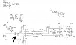
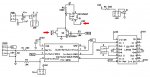
The schematic shows a circuit designed to monitor the condition of a Mercury switch (shown as a button in the schematic). To avoid using battery power while waiting for a event, I'm trying to use the two transistors as a switch activated by the Merc. switch. Once the program reaches the end, the last instruction will pull down the base of the NPN transistor.
When the gate of the PNP is pulled to ground I expected to measure a voltage equal or very close to V but nothing happens.

AUTO ON_OFF.jpg
This is the code I'm planning to use to avoid using power during the idle time between actuation of the Mercury switch.
Code:
[color=Navy]#picaxe [/color][color=Black]08m2[/color]
[color=Navy]#No_Data

      [/color][color=Blue]High C.4[/color]
[color=Black]Main:
      [/color][color=Green]'THE REST OF THE PROGRAM
      '**********************
      '**********************
      [/color][color=Blue]Low C.4[/color]
I am using a P chan Mosfet https://www.fairchildsemi.com/datasheets/ND/NDT452AP.pdf
 

srnet

Senior Member
Be aware you are mixing (and confusing) PNP\NPN Bipolar transistors and devices that are P channel MOSFETS.

If on the circuit you have shown the gate of the 45AT2 is grounded, by a wire or the switch, then the drain (VDD) should be very lose indeed to V, if its not forget about the rest of the circuit, concentrate on getting the P Channel MOSFET working first.
 

srnet

Senior Member
Looks like your FET is connected wrong, look at the integral diode.

Regards, Bear..
Looks right to me.

With the source higher than the drain, the diode will be non-conducting.

If it were the other way around, then VDD would be a diode drop below V, even when the MOSFET was off.
 
Be aware you are mixing (and confusing) PNP\NPN Bipolar transistors and devices that are P channel MOSFETS.

If on the circuit you have shown the gate of the 45AT2 is grounded, by a wire or the switch, then the drain (VDD) should be very lose indeed to V, if its not forget about the rest of the circuit, concentrate on getting the P Channel MOSFET working first.
I changed the value of R5 from 100K to 10K and the MOSFET is working. Next I will try to find out if the rest of the circuit will work.
 

srnet

Senior Member
I changed the value of R5 from 100K to 10K and the MOSFET is working. Next I will try to find out if the rest of the circuit will work.
The MOSFET should be quite happy with a 100K.

I would check what the gate voltage actually is with the switch closed, although you say it works, something is not quite right.

And the Transistor and base resistor could be replaced with a diode.
 

Hemi345

Senior Member
Slightly off-topic, but tie pins 10 and 15 of the L293D to ground for more power savings if channels 3 and 4 of that driver aren't going to be used.
 
srnet, Thank you for your input and desire to help. As an old man trying to learn a new subject, I can use all the help I can get.
The MOSFET should be quite happy with a 100K.

I would check what the gate voltage actually is with the switch closed, although you say it works, something is not quite right.
The voltage at the gate is .014V when the switch is closed.

And the Transistor and base resistor could be replaced with a diode.
The switch is on for 2 seconds. The first instruction on the program is High C.4. So that transistor should keep the Gate of the MOSFET down until the last instruction of the program.
That is what I'm trying to do.
 

srnet

Senior Member
srnet, Thank you for your input and desire to help. As an old man trying to learn a new subject, I can use all the help I can get.

The voltage at the gate is .014V when the switch is closed.


The switch is on for 2 seconds. The first instruction on the program is High C.4. So that transistor should keep the Gate of the MOSFET down until the last instruction of the program.
That is what I'm trying to do.
Yes, but you could control the gate of the MOSFET direct with a PICAXE pin.

At startup the PICAXE pin will be an input, so the resistor on the gate of the MOSFET will keep it off. Its then perfectly in order to control the MOSFET switch with a PICAXE pin, set it low for on, high (or input) for off.

With the switch there, it would be possible for the PICAXE pin controlling the gate to be high, so if the switch is pressed, that would not be good for the PICAXE pin. So you put a diode in-line with the pin, so it can pull the MOSFET gate low (to turn it on) and with the PICAXE pin high the diode does not conduct, so the resistor on the MOSFET gate keeps it off. Its the equivalent of a diode OR circuit.
 
srnet, Thank you again.
If I understood you correctly, the new circuit will look like this.
AUTO ON_OFF.jpg
Do I still need R3?

And the code
Code:
#picaxe 08m2
#No_Data

      Low C.4
Main:
      'THE REST OF THE PROGRAM
      '**********************
      '**********************
      High C.4
 
Top