Hi, cant seem to find anything definitive on using a SAA1064 with a large 7 seg LED display with 4 LEDs per segment (Vf > 5V). Seems like SAA1064 can operate at supply voltage up to 15 volts but I'm unclear on operation of SDA and SCL lines with a picaxe running with 5 volt supply. Thought to use a FET level converter between picaxe and SAA1064 but SAA1064 data sheet mentions protection diodes to ground which seem to limit voltages on SDA and SCL line to a max of 5.9 volts. Appreciate any tips or advice. Thanks. David.
SAA1064 large display
- Thread starter dworboys
- Start date
This application note might help, pages 13,14
http://www.nxp.com/documents/application_note/AN264.pdf
because the output drivers are "sinking", you can power the chip from 5V and sink the display drive current from some higher volatge source (with common ground of course)
http://www.nxp.com/documents/application_note/AN264.pdf
because the output drivers are "sinking", you can power the chip from 5V and sink the display drive current from some higher volatge source (with common ground of course)
Hi,
I think all that you need to do is connect the PICaxe and the I2C (SDA & SCL) pullup resistors (~4k7) to a 5 volts rail and you can then connect the SAA1064 supply rail to a higher voltage, i.e. sufficient to drive the 4 LEDs in series, together with the (not insignificant) additional voltage drops across the driver stages.
Cheers, Alan.
Some years back i did do a batch of home made PCBs for this driver and 4 x 7 seg displays, i did not do a schematic for the boards as they were very simple.
One board took the driver chip and the other board took the display chip, the display board stacked on top of the driver board and was joined via header pins on each end of the boards (KABCDEFG). This made up a smaller compact display module.
Both boards were single sided boards
Perhaps you can reverse engineer the design layout to answer your questions.
Both boards were powered from 5 volt same as the picaxe, the I2C bus had 4K7 pullup resistors fitted to the picaxe master board and not on the display boards, as there was more than 1x I2C device fitted to the circuit in use.
No other components were used other than what is shown on the PCBs.
View attachment 4 x 7 seg display.pdf
Hi,
How many digits are you using? For only (up to) two digits the segments can indeed be connected to a higher voltage than the chip, as below.
Cheers, Alan.
How many digits are you using? For only (up to) two digits the segments can indeed be connected to a higher voltage than the chip, as below.
But for more digits you need to multiplex with the additional pull-up pins (11 and 14).because the output drivers are "sinking", you can power the chip from 5V and sink the display drive current from some higher voltage source (with common ground of course)
Cheers, Alan.
Here is a data sheet i find a little less colourful but easier to follow for the SAA1064.
View attachment SAA1064.pdf
Im still unsure if the question is to driving a 4 x 7 seg module display, or a larger display made up of 4 x single 7 seg displays.
View attachment SAA1064.pdf
Im still unsure if the question is to driving a 4 x 7 seg module display, or a larger display made up of 4 x single 7 seg displays.
hippy
Ex-Staff (retired)
That I think is the problem; that there is no obvious separate power supply for chip (logic) and the displays, or, perhaps more accurately, when driving four separate 7-segment displays using MUX1 and MUX2, there is a question as to whether those MUX outputs can readily be used to control the external high-side transistor drives for the displays if that supply is separate and higher than the chip (logic) supply rail.Run the logic in the chip at 5V, same as Picaxe. No faffing about needed there for interfacing.
What you choose to supply the display elements with can be different.
For controlling just two 7-segment displays in static mode, where the device simply sinks each display, it seems the chip could be run at 5V with the display drive voltage higher, but again that isn't detailed in the datasheets. And isn't what the OP desires.
I suspect it is possible to run chip (logic) and display drive from (upto) 15V and simply connect SDA and SCL to a 5V PICAXE with pull-ups to 5V as Allycat suggests in post #3. The datasheets however, as noted by the OP, are not clear on that.
One arguably needs level-shifting when interfacing a 3V3 system to 5V system using the I2C bus and the same can be argued for interfacing a 5V PICAXE to a 15V driver chip.
Added: However; looking at the datasheet SAborn provides a link for in post #8, the SDA and SCL voltages are defined as absolute 0V to 5V, < 1V5 low, > 3V high, rather than with respect to VCC. That would suggest to me that as Allycat suggests in post #3 would work.
I think it's going to come down to trying it, seeing if it works.
Last edited:
Hi,
I think that I have enough "inside information" to say that what I described in #3 will work fine. The chip will have an internal regulator for the "logic" part of the circuit, you just need to comply with the I2C input level requirements in the data sheet.
The only factor to beware is that the high-side multiplex drivers (pins 11 & 14) are "emitter followers" (driven from an integrated PNP pull-up) so may drop several volts. Combined with the integrated low-side current-source drivers, 8 volts is perhaps about the most you will get across the LED(s) with a 12 volt supply. That should be OK for (4 series) Red LEDs, but may be insufficient for other colours (particularly white and blue).
For a higher drive voltage, or more efficiency, you could/should use a pair of high-side PNP (or PMOS) pullup transistors. They would (normally) each be driven by a small low-side NPN (with a base resistor to the Mux output, or better a current-source configuration) and then you could run the SAA 1064 from 5 volts if you so wish.
Cheers, Alan.
Last edited:
Thanks AllyCat. What you have described is similar to one channel of a UDN2981 Source Driver (see attached pdf page 3). I should be able to connect the SAA1064 Mux lines directly to two inputs of a UDN2981 and then I can have Vs of the UDN2981 set at any voltage I need and run the SAA1064 at 5V. I know its a bit of overkill using a UDN2981 but its easier to breadboard than building it up from discrete parts. David.
Attachments
-
345.5 KB Views: 11
Hi,
Well, the UDN appears also to use an emitter follower (actually a Darlington) output stage, so the voltage drop may not be much better than the SAA mux outputs. The UDN data sheet specifies a typical drop of 1.6 V at 100 mA.
A (saturated) medium current PNP (e.g. BC327) should drop at least a volt less than that. Probably just needs a NPN (e.g. BC548) "current source" driver interface (i.e. SAA mux output directly to base, emitter via 1k to ground, collector directly to PNP base). But perhaps an additional pull-down resistor on the SAA output (e.g. across the NPN base-emitter) would be wise (in case of high temperature leakage currents).
But for a "one-off" design, use whatever you feel comfortable with.")
Cheers, Alan.
Well, the UDN appears also to use an emitter follower (actually a Darlington) output stage, so the voltage drop may not be much better than the SAA mux outputs. The UDN data sheet specifies a typical drop of 1.6 V at 100 mA.
A (saturated) medium current PNP (e.g. BC327) should drop at least a volt less than that. Probably just needs a NPN (e.g. BC548) "current source" driver interface (i.e. SAA mux output directly to base, emitter via 1k to ground, collector directly to PNP base). But perhaps an additional pull-down resistor on the SAA output (e.g. across the NPN base-emitter) would be wise (in case of high temperature leakage currents).
But for a "one-off" design, use whatever you feel comfortable with.
Cheers, Alan.
marzan
Senior Member
I found this board the other day. I have ordered a couple. everything you need for larger 8 digit 7 seg display and can handle 500ma at 24v per segment !!. Figure it is a nice neat board with room for a picaxe underneath .....
https://www.tindie.com/products/rajbex/serial-driver-for-large-seven-segment-led-display-modules/
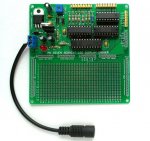
I know its not the same driver chip that you are using, But figure someone trolling through the posts might like the look of it
Marz.
https://www.tindie.com/products/rajbex/serial-driver-for-large-seven-segment-led-display-modules/
I know its not the same driver chip that you are using, But figure someone trolling through the posts might like the look of it
Marz.