mikepanchaud
New Member
hi,
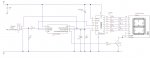
I'd like to use port 1 (pin 6) on a Picaxe 08M2 as an ADCinput using a thermister and resistor potential divider, BUT also use this pin to beep a piezo sounder.
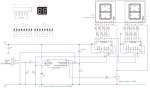
All the other ports 0, 2 and 3 are tied up with driving a seven segment display. Port 2 and 4 to reset and clock a CD4026 driver and port 2 dimming the dissplay with pwm.
I've tried this and it works on a bread board, but I'd like to ask is this good / bad practice? Does using the same port to beep the piezo then immediatley use it to read an analogue value cause accuracy problems?
I'm going to build it any way and see what happens and will report back if anyone is interested. The project btw is to measure the temp of a cup of tea and beep when correct temperature to drink!
mike.
I'd like to use port 1 (pin 6) on a Picaxe 08M2 as an ADCinput using a thermister and resistor potential divider, BUT also use this pin to beep a piezo sounder.
All the other ports 0, 2 and 3 are tied up with driving a seven segment display. Port 2 and 4 to reset and clock a CD4026 driver and port 2 dimming the dissplay with pwm.
I've tried this and it works on a bread board, but I'd like to ask is this good / bad practice? Does using the same port to beep the piezo then immediatley use it to read an analogue value cause accuracy problems?
I'm going to build it any way and see what happens and will report back if anyone is interested. The project btw is to measure the temp of a cup of tea and beep when correct temperature to drink!
mike.