Nicholas23
New Member
Removed
0000000000
0000000000
Last edited:
What sort of RGB LED? A simple answer is directly via a 100 ohm resistor to 3 outputs. then turn on the colour you need.Hi all. I am wondering if there is any way to interface a picaxe 28X1 to a RGB LED. I realize it can't be directly connected, but are there any IC's
or something? Or can't it be done? There must be some way.
I disagree with that but what would you expect from people who freely give their time when they don't have to, who try to help the best they can but don't have all the answers ?Wowwwwwwwwww, nobody on this bloody website is of any help
I'm not sure what a "real answer" is or why you think anyone here would have one. This forum is primarily about mentoring and helping people help themselves. Contributors do the best they can and point to sources of information which they hope will help; it might it might not. If really lucky then someone may say "I've done that, here's how to do it", second best is people pointing to the work others have done on RGB LED interfacing already.I also have a thread on RGB led interfacing and everyone just gives roundabout, stupid answers. Like have you checked the manual?, or you just use a resistor and a led... we know how to hook up the RGB, we arn't idiots, we want to know how to PWM the 3 seperate pins to blend colors. The picaxe 28x1 can only pwm out on 2 pins so that wont work, and software written pwm doesn't have enough accuracy or speed to work properly. All Nicolas and I want to know is... how is it done, with what chip and what circuit. So if anyone could post a real answer it would be greatly appreciated.
")
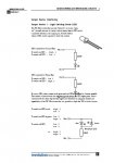
'Forum Tu 100608  rgb Hippy/Tom L
#picaxe 18x

symbol rTime = b0
symbol gTime = b1
symbol btime = b2
symbol xtime = w2
symbol R_LED = 0
symbol G_LED = 1
symbol B_LED = 2
symbol dummy = 3

setfreq m8
 main:
 for rTime = 10 to 255 step 10
 for gTime = 0 to 255 step 10
 for bTime = 0 to 255 'step 5

 xTime = 766 - rTime - gTime - bTime
 PulsOut R_LED, rTime
 PulsOut G_LED, gTime
 PulsOut B_LED, bTime
 PulsOut DUMMY, xTime
 next
 next
next#picaxe 18x
'mouldy green rgbled OR r+g+b
'resistors need adjustment
symbol rTime = b0
symbol gTime = b1
symbol btime = b2
symbol xtime = w2
symbol R_LED =0
symbol G_LED =1
symbol B_LED =2
symbol dummy = 3
setfreq m8
do
rTime = 60
gTime = 250
bTime = 80
xTime = 766 - rTime - gTime - bTime
PulsOut R_LED, rTime
PulsOut G_LED, gTime
PulsOut B_LED, bTime
PulsOut DUMMY, xTime
loop
 PulsOut 4, bTime
 PulsOut 5, gTime
 PulsOut 6, rTime
PulsOut 7, xTimeThat's because PULSOUT only works on 'the default output pins', but with a little arm twisting 8 x RGB may be doable ...Unfortunately, the program won't work on a 14M (Man. 2 page 113)
I can understand your frustration when you are looking for a specific answer but there are a couple of things to bear in mind ...I'm grateful for your construtive answers I'm just not a fan of people beating around the bush. If you dont know how to do it... don't post.
Please can you post both the code and the schematic please?I kbow this is an old thread. I thought it would be cool if one of my halloween projects (animated with) had colour changing eyes. I have some RGB LED's (common anode) and have them hooked up to the B pins (R-B.4, G-B.5, B-B.7, Anode- B.6) on a CHI030 (just the pins, not thru the darlington). I am using the code set out by eclectic in post #22 of this thread, modified , of course, for the 18M2. When the code runs, only the Red portion lights up. Am I missing something?
Would this wiring not be overloading the Anode pin B.6, once more than 1 led was lit, as if all 3 leds draw 20ma each that would be 60ma through B.6 which is 3 times the rating of B.6.have them hooked up to the B pins (R-B.4, G-B.5, B-B.7, Anode- B.6) on a CHI030 (just the pins, not thru the darlington).
'Forum Tu 100608  rgb Hippy/Tom L, modified for Picaxe 18M2 by Pat13
#picaxe 18M2

symbol rTime = b0
symbol gTime = b1
symbol btime = b2
symbol xtime = w2
symbol R_LED = B.4
symbol G_LED = B.5
symbol B_LED = B.7
symbol dummy = B.6

setfreq m16
 main:
 for rTime = 10 to 255 step 10
 for gTime = 0 to 255 step 10
 for bTime = 0 to 255 step 5

 xTime = 766 - rTime - gTime - bTime
 PulsOut R_LED, rTime
 PulsOut G_LED, gTime
 PulsOut B_LED, bTime
 PulsOut DUMMY, xTime
 next
 next
nextIs there a way this can be done thru the darlington on the CHI030?Would this wiring not be overloading the Anode pin B.6, once more than 1 led was lit, as if all 3 leds draw 20ma each that would be 60ma through B.6 which is 3 times the rating of B.6.
The original code and circuit was designed around Common cathode LED's.Is there a way this can be done thru the darlington on the CHI030?
#picaxe 18M2

symbol rTime = b0
symbol gTime = b1
symbol btime = b2
symbol xtime = w2
symbol R_LED = B.4
symbol G_LED = B.5
symbol B_LED = B.6
symbol dummy = B.7 ; unconnected

setfreq m16

 main:

 for rTime = 10 to 255 step 10
 for gTime = 0 to 255 step 10
 for bTime = 0 to 255 step 5

 xTime = 766 - rTime - gTime - bTime

 PulsOut R_LED, rTime
 PulsOut G_LED, gTime
 PulsOut B_LED, bTime
 PulsOut DUMMY, xTime

 next
 next
 next

goto main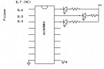 ) but that is going to work for me. I assume that if I want to change the hue, it is thru changing the values of rTime, bTime and gTime. Correct me if I'm wrong but STEP is what is making the colors cycle and if I change that value, the colours will change quicker or slower?